Power Electronics Design with NI Multisim
Overview
NI Multisim is a powerful tool used to simulate and prototype power electronics circuit designs. Multisim has large database of configurable power component modelse along with existing SPICE models from various semiconductor manufacturers. The powerful Multisim simulation enables the evaluation of different power circuits of different ratings at an early design stage. You can use models for IGBT and MOSFET switches, electro-mechanical components, different active and passive components, and switching controllers to accurately evaluate power electronics systems.
Contents
- Introduction to Power Electronics Design
- Multisim Power Components
- Simulation Analyses
- Application Examples
Introduction to Power Electronics Design
Power electronics designers are typically working on Switch Mode Power Supplies (SMPS) systems to perform multiple types of power conversions:
- AC to DC power (rectifiers)
- DC to AC power (inverters)
- DC to DC power (regulators)
These analog circuits require advanced modeling of component behavior such as non-linearity, switching losses, and thermal behavior. While at the heart of the system, runs advanced control algorithms. Different controllers are available in the market, such as CPLDs, microprocessors, and DSPs, yet FPGA remains the most powerful technology.
Due to the increasing complexity of power systems and the costs involved in prototyping and testing preliminary designs, engineers are turning more to computer based simulations for assistance in the design phase.
SPICE is the dominant technology for simulating power circuits. However, there are two aspects that make it more challenging to simulate power circuits than low-power analog circuitry in a SPICE simulator; the quality of the component models, and the accuracy of the transient time simulation of the SPICE engine. In Multisim, we account for both of these aspects to guarantee a best-in-class simulation and analysis of power electronics circuits.
In addition, Multisim is fully integrated with NI Ultiboard to help you complete your design with powerful PCB layout and routing capabilities.
Multisim Power Components
In Multisim we have added a large number of components that are considered the building blocks of any power circuit. This section points out these parts in greater detail
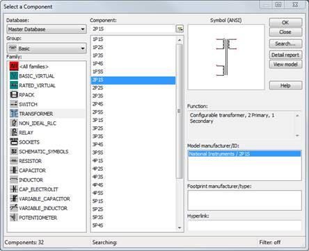
Transformers
This component is based on a general model that can be customized for different applications. It is implemented using a conceptual magnetic core and coreless coil building blocks, together with resistors and inductors. Using this transformer, you can can model physical effects such as nonlinear magnetic saturation, primary and secondary winding losses, primary and secondary leakage inductances, and core geometric size.
All these modeling options give Multisim a big competitive edge over other tools. The transformer also allows the modeling of multiple windings.
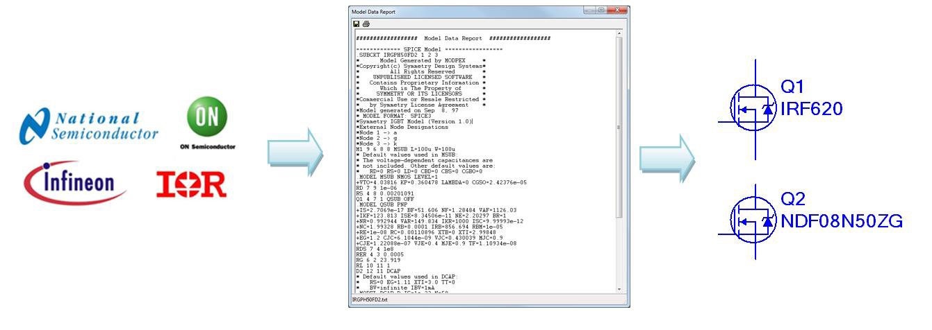
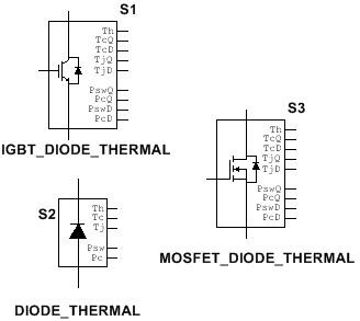
Switches
Multisim’s database include a variety of models for MOSFET and IGBT switches from leading semiconductor manufacturers such as NXP, International Rectifier, and Texas Instruments. The models are provided by the manufacturer and validated by the Multisim R&D team. NI forges strong relationships with these partners to continuously improve Multisim’s database.
Also Multisim comes with over 500 new Infineon MOSFETS, with up to 3 levels of model complexity for intricate power applications such as thermal modeling.
Examples of these switches are under the transistors group in Multisim’s database.
In addition, Multisim includes generic models for MOSFET switches and IGBTs. These components model transistors for system-level simulations in case manufacturer models are not available.
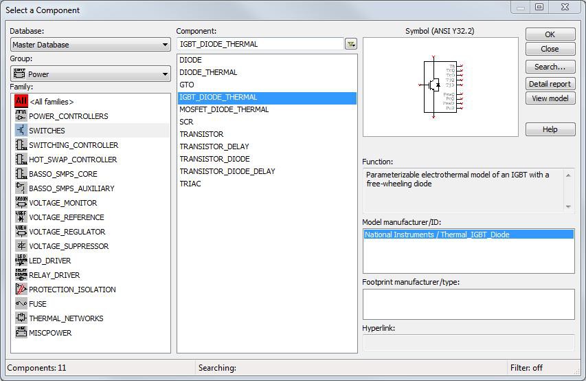
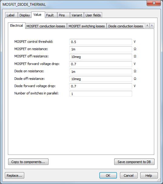
In Multisim 13.0 new customizable diode, IGBT, and MOSFET components with thermal behavior information have been added. These components allow you to accurately evaluate conduction and switching losses and SMPS circuits thermal behavior.
In addition to the switches generic models, Multisim includes models for Silicon Controlled Rectifiers (SCR), and Gate Turn Off (GTO) switches. With these components, you could accurately simulate your AC control or high-power rectification circuit performance.
Gate Drivers
Multisim’s library is updated with a variety of gate driver components necessary for use with any power switches. The most complicated models are from ON Semiconductor and International Rectifier.
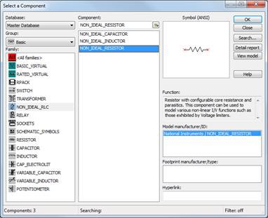
Passive Components (RLC)
Parasitic behavior of passive components plays an important role in the performance of power circuits. This is why in Multisim components have been created to model parasitics of resistors, capacitors, and inductors. These components could be found in the component database under the Basic group in the NON_IDEAL_RLC family
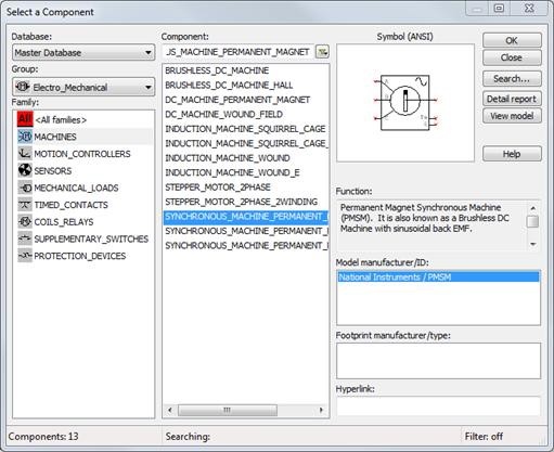
Motors
Many engineers working on electro-mechanical systems find it challenging to predict the electric circuit performance with mechanical parts such as DC machines, stepper motors, and induction machines. To complete the power electronic solution commonly used to drive motors that draw very high current or fed by 3-phase generators, Multisim includes components that models for such mechanical parts of the system.
The component group Electro_Mechanical in Multisim’s database contains models for machines, speed sensors, motion controllers, and other parts that could be used for this purpose.
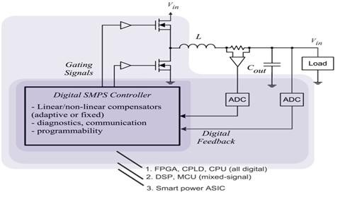
Controller Design in Multisim
Open-loop SMPSs rely on feeding a constant voltage to the input of a transformer or inductor, and assume that the output will be correct. This type of SMPS designs is not practical and is no longer used in industrial applications.
Closed-loop SMPSs are the more practical designs where the controller is the feedback circuit that monitors the output voltage and compares it with a reference desired voltage. Based on the design requirements and the results of this comparison, the controller is able to make switching decisions and feed input back into the analog circuit to either switch a transistor on/off or activate/deactivate certain parts of it. Depending on the design and the safety requirements, the controller may contain an isolation mechanism to isolate it from the DC output.
The remainder of this section discusses different options of controller design in Multisim.
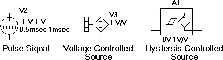
Arbitrary Signal Generators
A controller behavior could be modeled at a very basic level by arbitrary digital signal generators. Multisim includes a variety of these parts that allow the user model a fed-back signal to control the switching of the analog circuitry.
Generic Controllers
Pulse Width Modulation (PWM) is commonly used for controller logic. By switching an input voltage with the appropriate duty cycle, the output will approximate a voltage at the desired level.
Multisim includes PWM, PWM complementary, and PWM three-phase generators. These components model simple PWM generators. The PWM component's model consists of a comparator and a triangular waveform generator.
The Power Controllers component family includes the following switching controllers:
- Phase Angle Controller
- Phase Angle Controller Two-Pulse
- Phase Angle Controller Six-Pulse
- Pulse Width Modulation Components
- PWM Sinusoidal Three-Phase
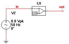
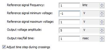
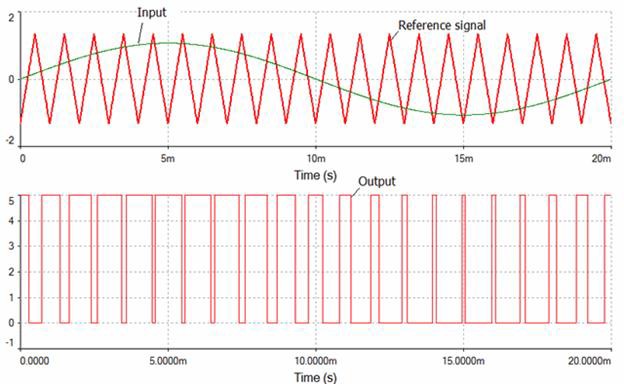
Example of a PWM source in Multisim:
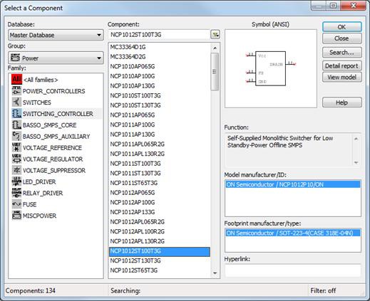
ON Semiconductor Controllers
ON Semiconductor offers controllers and regulators for a variety of advanced topologies, enabling the development of highly efficient power supplies. Multisim is equipped with a large number of standard models for these SMPS controllers. All the models are verified and tested to guarantee an accurate evaluation of the system behavior. The types of controllers include:
- Fixed frequency flyback & forward PWM controllers, including current mode and voltage mode devices
- Off-line, switching regulators, including current mode, voltage mode, and gated oscillator devices
- Variable CRM, CCM, and DCM power factor controllers that enable power factor correction
- Secondary side, synchronous rectification controllers
LabVIEW and Multisim Co-simulation
With the recent evolvement in the renewable energy industry, Field Programmable Gate Array (FPGA) technology is becoming the most powerful technology for SMPS control. NI LabVIEW offers a graphical environment for FPGA development that integrates with a wide variety of NI embedded platforms that fit almost every embedded application requirement using state of the art FPGA chips from Xlinx.
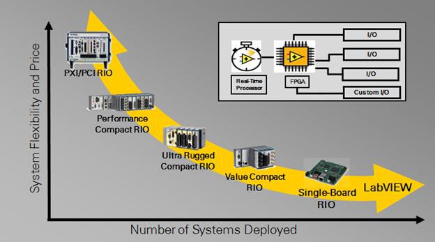
Prior to the system hardware deployment, the ability to accurately simulate the FPGA control systems with SPICE models of the analog plant is extremely valuable. Multisim and LabVIEW enable an unparalleled system simulation of analog circuitry and FPGA control on the desktop. Both simulation engines are running point-by-point negotiating a variable time-step simulation and allowing the accurate prediction of the system behavior.
Check this application of 3-phase back-to-back inverters to model simulate and prototype renewable energy systems.
To learn more about the NI solution for power electronics design and test, visit NI’s power development community page.
Simulation Analyses
Multisim features a comprehensive suite of simulation tools and an expandable selection of custom analyses for examining and optimizing circuit performance.
The most critical analysis in the evaluation of power circuit performance is the transient analysis. It is used to visualize the critical voltage transitions at different nodes of the circuit from one state to another and illustrate how the circuit converges to its steady state.
In Multisim, designers could vary different transient simulation parameters to guarantee a higher quality of the simulation (over the expense of simulation time). Dealing with these parameters requires some basic understanding of SPICE simulation. You can find these under Simulate/Interactive Simulation Settings on the Analysis options tab. Use custom settings and click the Customize box.
| Parameter | Function | Action |
| RELTOL | Relative Error Tolerance |
|
| GMIN | Minimum circuit conductance |
|
| IC | Initial node voltages |
|
| ITL | Upper Transient Iteration Limit |
|
| METHOD | Time Step Integration Method |
|
Table 1. Simulation Parameters That Must Be Set If the Circuit Fails to Converge
Read more about different types of analyses in Multisim.
Learn about the fundamentals of SPICE simulation.
Application Examples
Higher efficiency, higher speed, and accurate control require powerful simulation capabilities and an optimized design environment to help designers become more productive in their prototyping approaches. The capability of modeling these power components in Multisim takes advantage of the design and simulation fidelity of circuits like single-phase and 3-phase rectifiers; inverter circuits; and buck, flyback, and forward converters.
Below are snippets of vital power electronics circuits. A snippet is a PNG image that you can simply drag and drop into Multisim to load the design and the file is ready to run in Multisim.
3-Phase Inverter Design with Thermal Modeling and Switching and Conduction Losses
This sample shows a thermal analysis of a three-phase IGBT inverter. The IGBTs are the FS100R12KE3 parts from Infineon. Parameters for the thermal IGBT model are taken entirely from the datasheet.
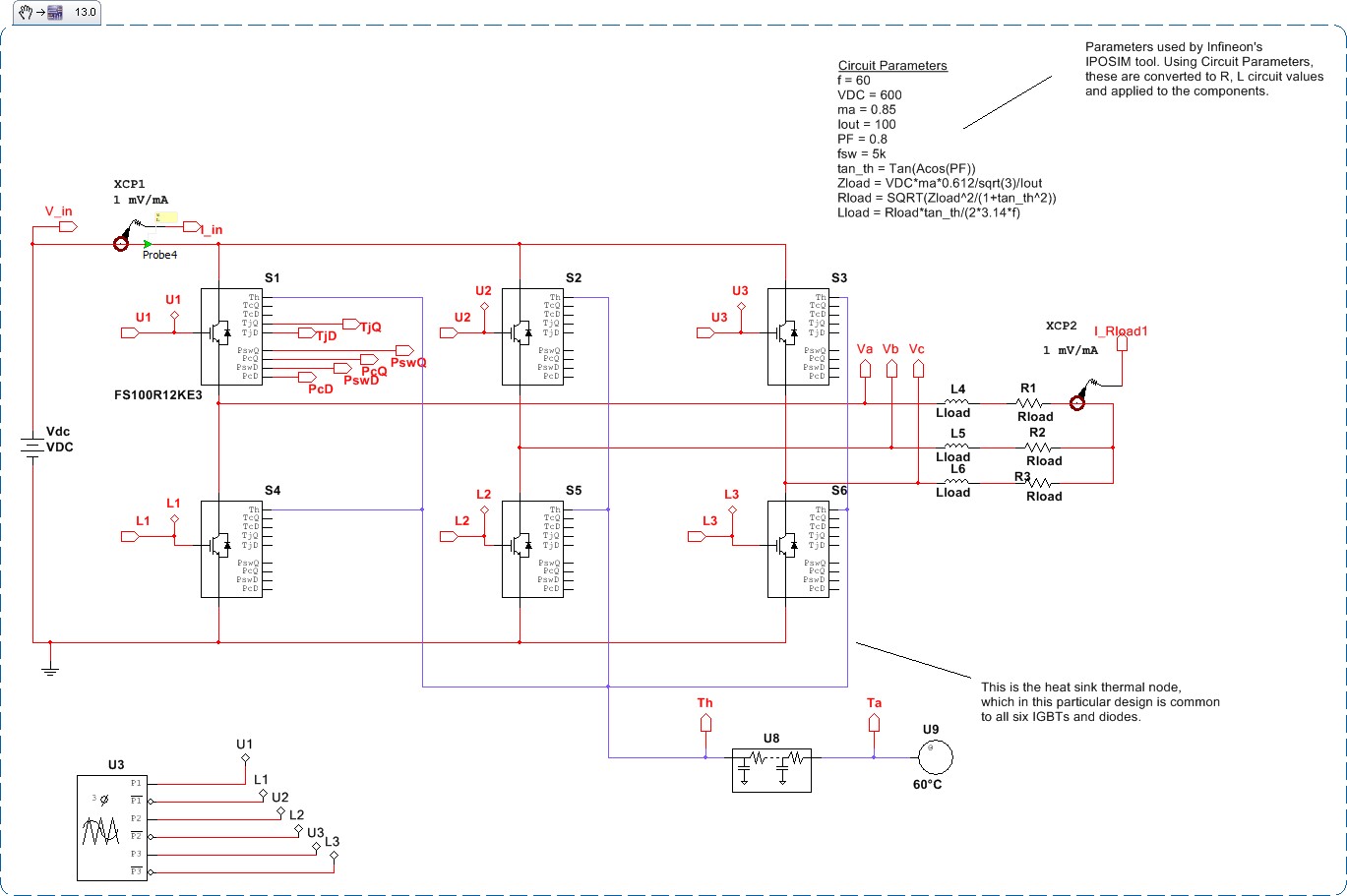
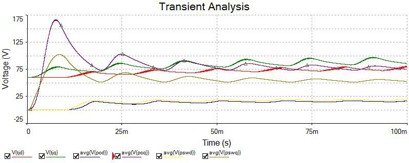
Running a transient simulation allows you to learn about the heating of the IGBT junctions, as well as how much power was lost during switching and conduction.
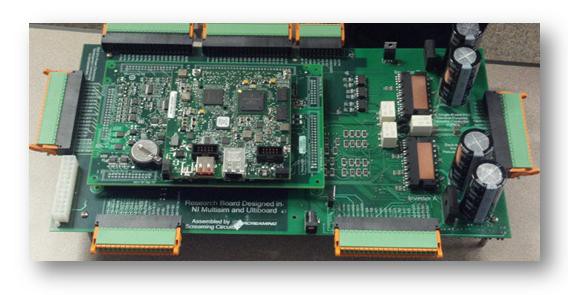
Prototyping application with Ultiboard and NI’s General Purpose Inverter Controller (GPIC)
Learn more about the complete NI solution for power design with Multisim simulation of inverter analog plants, LabVIEW FPGA controller design and rapid prototyping with the NI GPIC and Ultiboard layout capabilities, here.
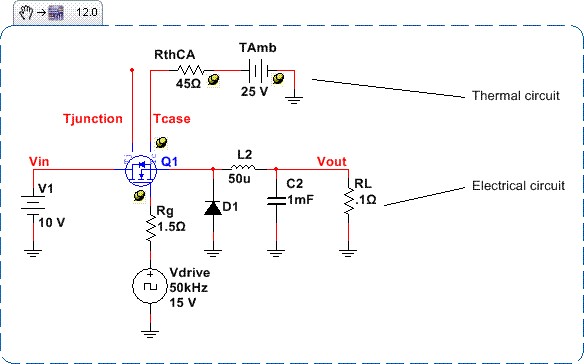
Thermal Modeling Using New Infineon MOSFET Models for a Buck Converter
This design demonstrates how to use the thermal modeling features of the Infineon Level 3 electro-thermal models. Run the transient simulation of this circuit to evaluate the thermal performance of it on the desktop.
Next Steps
- Learn more about using Multisim for education
- Download Multisim
- Learn more about the thermal effects of power electronics
- Watch an introductory tutorial video about power electronics co-simulation with Multisim and LabVIEW
- Watch a webcast about efficient fast-switching power converter design with Multisim