How to Connect Signals to the NI 2529
Contents
- Overview
- NI 2529 Terminal Blocks
- Signal Connection with Terminal Blocks
- Custom Termination Options for the NI 2529
- Related Resources
Overview
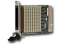
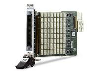
The NI PXI/PXIe-2529 (NI 2529) is a high-density matrix built to serve high-channel-count switching applications. The module is a 2-wire matrix, configurable with front-mounting terminal blocks to achieve two different matrix configurations (4x32 and 8x16). The NI 2529 is designed to work well with both low and high-voltage levels. For low-voltage measurements, the NI 2529 uses relays with low thermal offset to ensure accurate measurements. These same relays can handle up to 150 Vrms or 150 VDC.
NI 2529 Terminal Blocks
There are three terminal blocks available for the NI 2529:
TB-2634: 4x32 2 -wire, dual 4x16 2-wire
TB-2635: 8x16 2 -wire
TB-2636: 4x32 2 -wire
The NI 2529 can be used in 4x16 2-wire mode by removing resistors from the TB-2634. This will be covered in the Signal Connection with Terminal Blocks portion of the tutorial.
TB-2634
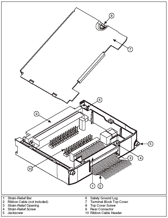
The NI TB-2634 configures the NI 2529 high-density matrix switch as a 4x32 (2-wire) matrix. Connections are made with ribbon cable headers inside the housing.
Below is a summary of how to connect signals to a PXI/PXIe-2529 using a TB-2634. For more information than is provided in this tutorial on connecting signals using the TB-2634 please see the TB-2634 Installation Instructions.
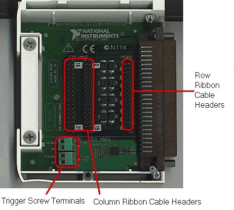
The figure below outlines the main components of the TB-2634:
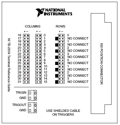
The figure below clearly outlines how the ribbon cable headers on the TB-2634 map to the 2-wire columns and rows of the NI 2529:
The TB-2634 will be used with the NI 2529 when a 2-wire 4x32 or a 2-wire 4x16 matrix topology is required.
In the 2-wire 4x32 topology the columns, rows and banks are arranged as follows:
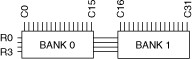
Below is an image of the TB-2634 outlining the various connections:
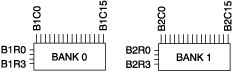
In 2-wire 4x16 Matrix topology, the columns, rows and banks are arranged as follows:
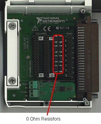
To utilize the NI 2529 in 2 -Wire Dual 4x16 Matrix Topology, eight surface mount zero Ohm resistors must be de-soldered and removed from the board. These resistors are outlined in the following figure:
For both the 2-wire 4x32 or a 2-wire 4x16 matrix topologies connecting signals to the TB-2634 involves using ribbon cable sockets. The vendors of compatible sockets can be seen on the following table:
Accessory
| Manufacturer
| Manufacturer Part Number
|
0.1 in. 2 × 16 low-profile ribbon cable socket
| Samtec
| |
0.1 in. 2 × 16 low-profile ribbon cable socket
| Samtec
|
A low-profile ribbon cable socket will be required to connect signals to columns 0-15, columns 16-31 and rows 1-4 respectively.
The ribbon cable itself is standard 16-lead ribbon cable and can be found at most common electronic supply store.
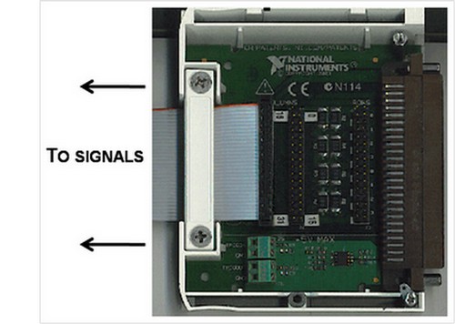
In the image below, a low-profile ribbon cable socket has been connected to columns 16-31 of the TB-2634:
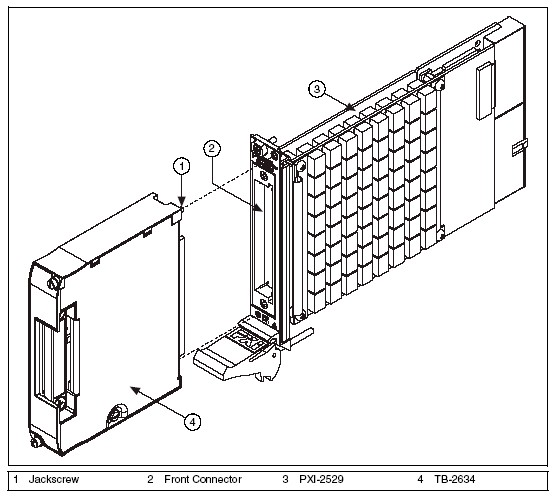
To connect signals to the NI 2529 via the TB-2634, attach low-profile ribbon cable sockets (with corresponding ribbon cable) into the desired set of columns and rows. Ensure that the ribbon cables are properly reinforced by the strain relief bar, and then attach the terminal block cover. The terminal block can then be connected directly to the switch via the mating connectors as shown in the following figure:
TB-2635
The NI TB-2635 configures the NI 2529 high-density matrix switch as an 8x16 (2-wire) matrix. It provides direct signal wire connections to the screw terminals inside the terminal block.
Below is a summary of how to connect signals to a PXI/PXIe-2529 using a TB-2635. For more information than is provided in this tutorial on connecting signals using the TB-2635 please see the TB-2635 Installation Instructions.
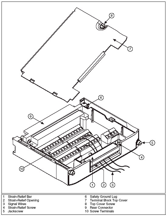
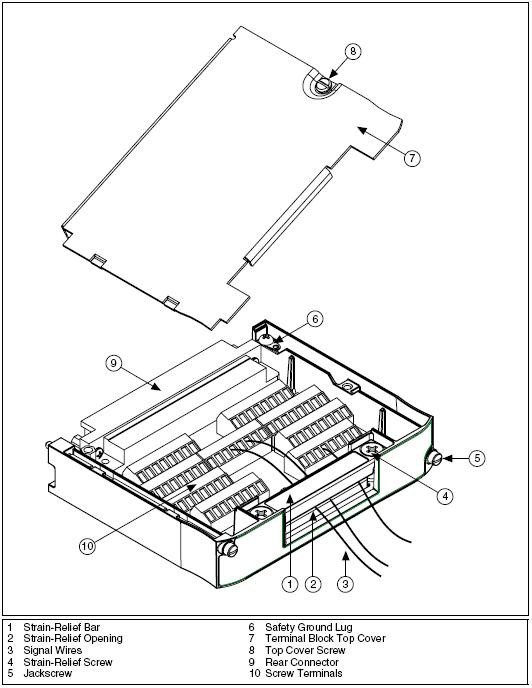
The figure below outlines the main components of the TB-2635:
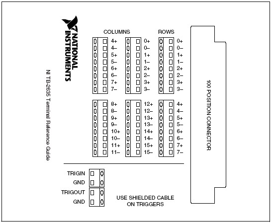
The figure below outlines how the screw terminals on the TB-2635 map to the 2-wire columns and rows of the NI 2529:
The TB-2635 is used with the NI 2529 when an 8x16 matrix topology is required.
In this topology the columns, rows and banks are arranged as follows:

Below is a actual image of the TB-2635 outlining the various connections:
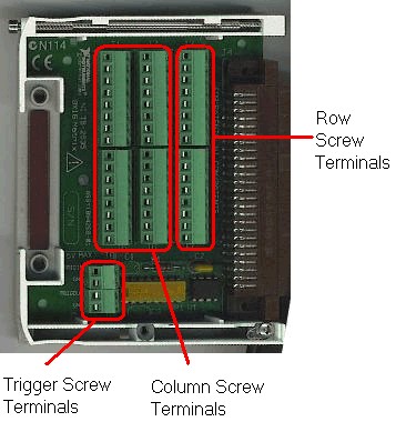
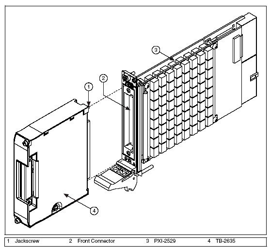
To connect signals to the NI 2529 via the TB-2635, screw in the 2-wire leads into the corresponding rows or columns as required, ensure that the leads are properly reinforced by the strain relief bar and then attach the terminal block cover. The terminal block can then be connected directly to the switch via the mating connectors as shown in the following figure:
TB-2636
The NI TB-2636 configures the NI 2529 high-density matrix switch as an 4x32 (2-wire) matrix. It provides direct signal wire connections to the screw terminals inside the terminal block.
Below is a summary of how to connect signals to a PXI/PXIe-2529 using a TB-2636. For more information than is provided in this tutorial on connecting signals using the TB-2636 please see the TB-2636 Installation Instructions.
The figure below outlines the main components of the TB-2636:
The figure below outlines how the screw terminals on the TB-2636 map to the 2-wire columns and rows of the NI 2529:
Signal Connection with Terminal Blocks
The NI 2529 is made up of two banks of matrices which individually have 4 rows and 16 columns. The TB-2634, TB-2635 and TB-2636 determine how these two banks are arranged in respect to each other and thus their corresponding topology.
The TB-2636 is used with the NI 2529 when an 4x32 matrix topology is required.
In this topology the columns, rows and banks are arranged as follows:
The TB-2636 has row, column, and trigger screw terminals similar to those seen in the actual image of the TB-2635. However, they are laid out as seen in the last figure of the NI 2529 Terminal Block Section above.
To connect signals to the NI 2529 via the TB-2636, screw in the 2-wire leads into the corresponding rows or columns as required, ensure that the leads are properly reinforced by the strain relief bar and then attach the terminal block cover. The terminal block can then be connected directly to the switch via the mating connectors as shown in the following figure:

Custom Termination Options for the NI 2529
The NI 2529 can also be utilized without the TB-2634, TB-2635, or TB-2636.
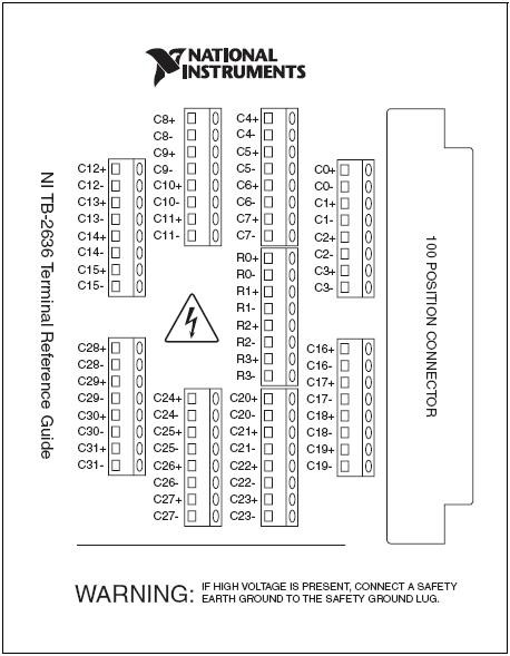
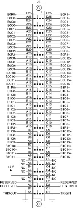
By using a compatible mating front panel connector, users can develop their own terminal block. A custom terminal block can connect and arrange any of the rows and columns of the two banks of the NI 2529 as required. The connector used on the NI 2529 is 100-Pin HDI.
Below is a figure of the pinouts for the NI 2529:
Vendors of compatible mating front panel connectors can be seen on the following table:
Accessory
| Manufacturer
| Manufacturer
Part Number |
100-Pin HDI Right Angle Mating Connector
| NI
| |
Mating front panel connector, vertical
| AMP
| 533285-1
|
Mating front panel connector, right-angle
| AMP
| 532903-2
|