Acquiring from FireWire® Cameras with NI-IMAQdx and Legacy NI-IMAQ for IEEE 1394
Overview
Contents
- Introduction
- IEEE 1394 Technology
- DCAM Specification for IEEE 1394 Cameras
- NI-IMAQdx
- Hardware Options
- Installing, Configuring and Using Your Camera
- IEEE 1394 Camera Bandwidth Table
Introduction
Because of their ease of use and standard interface, IEEE 1394 cameras are gaining rapid acceptance in the Machine Vision Industry. NI has developed a hardware driver that allows users to control IEEE 1394 cameras through an easy API. This document discusses some of the technical details of IEEE 1394 cameras and how to use them with the NI driver.
IEEE 1394 Technology
History:
IEEE 1394, also known as FireWire (or I-Link for sony devices), is a high-performance serial bus originally developed by Apple Computer in the year 1989 as a general purpose, high-speed serial bus. There was significant excitement about the bus and how it would best fit into the PC market. For a long time, there were questions about how it would compare with another new technology, USB. Eventually, USB became the primary serial bus for low-speed I/O, including mouse and keyboard connectivity. IEEE 1394 became more popular for higher bandwidth applications, specifically digital video and interfacing to camcorders. Soon after, industrial cameras adopted the bus too, and now there are hundreds of IEEE 1394 cameras available on the market.
Features:
The IEEE 1394 bus has several characteristics that make it easier to use than some of the traditional internal PC buses such as PCI and ISA. Devices that connect using IEEE 1394 are hot-pluggable, so they eliminate the need to shut down the PC to add or remove a device. The buses also have automatic device detection, meaning that the user does not have to manually configure his device once he plugs it in. The software should detect and install the device on its own.
The bus is relatively high-speed compared to RS232 or USB, with rates up to 400 Megabits per second for IEEE 1394a and 800 Megabits per second for IEEE 1394b. IEEE 1394 cables are available as either a 4-wire or 6-wire options. The 4-wire bus does not provide for power over cable, but the 6-wire version does. Communication is peer-to-peer, meaning that a camcorder can communicate with a VCR without a PC to conduct communication. It has the addressing capabilities for 1,023 busses with up to 63 devices per bus. However, when connecting multiple devices, there is a finite bandwidth available despite the addressing capabilities.
Data can be transferred over various distances. The standard IEEE 1394 cable is 4.5 meters. By using wireless technology or by placing hubs between IEEE 1394 cables, you can extend the distance of data transfer. Here are some different options when connecting IEEE 1394 device over long distances.
- 42 m (wire, up to 4 m between two nodes)
- 100+ m optical (NEC)
- 20+ m Wireless (Philips)
Asynchronous Transfer:
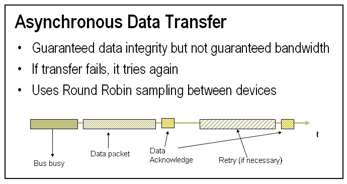
The IEEE 1394 bus provides two means of data transfer: asynchronous, which guarantees delivery, and isochronous, which guarantees bandwidth. Asynchronous data transfers guarantee that all data is transferred correctly by means of a data acknowledge packet from the recipient. If a device is set up for asynchronous transfer mode, and it does not get a data acknowledge after sending data, the device retries the command. This mode of data transfer guarantees that data has been transmitted. But, because retries are a possibility, there is no guarantee of bandwidth.
The following is an extreme example that illustrates guaranteed data integrity, but not bandwidth. Assume there are ten devices on the bus. Nine of the devices are slow and need 100 KB/s. One is fast and requires 6 MB/s. The total data that needs to be transported is approximately 7 MB/s. At first glance, you may think that this setup would not be a problem for a bus that can support 50 MB/s. However, in asynchronous transfer mode, IEEE 1394 uses round-robin bus access. Assume that each packet size is 1KB, and each device takes 25 microseconds to transfer its data. You can see that every 250 microseconds, the fast device would be allowed to send its 1KB packet, giving a throughput of only 4MB/s. The device would not transfer all of it’s data.
Isochronous Transfer:
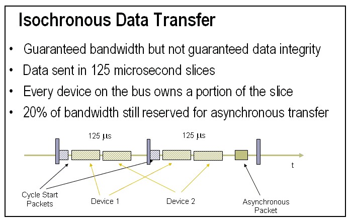
Isochronous data transfer guarantees bandwidth but not data integrity. As each device is placed on the bus, it requests bandwidth on the bus. The amount of bandwidth the device requests is determined by its packet size (in KB/packet). The bus is divided into 125 microsecond cycles. Each cycle begins with an Asynchronous cycle start packet. Devices that have requested isochronous bandwidth are guaranteed a single packet during each cycle. Once the packets are sent from each device, the remainder of the cycle is left for any other asynchronous transfers that need to take place. Overall, approximately 80% of each cycle is dedicated to isochronous data transfers. Because the recipient does not acknowledge that it receives a packet, there is no guarantee that the data made it across the bus. However, data received at one end is guaranteed to be in time with the data transmitted. In most cases (particularly those configurations that have only two devices on the bus), the transmission is successful.
IEEE 1394 devices may be capable of transferring data at certain rates, but since isochronous transfer splits this up into cylces, the actual throughput is calculated differently. Since every cycle of isochronous transfer is 125 microseconds, you will have 8000 cycles in a second. Also, each device sends 1 packet per cycle. Therefore, the throughput in Bytes per Second can be determined by the packet size of the device in Bytes multiplied by 8000.
Bandwidth:
The total bandwidth for the bus is shared among all devices on a 1394 bus. The 1394a specification allows devices that run at 400, 200 and 100 Mb/s while the 1394b specifications allows the additional 800 Mb/s speed. The 200 and 100 configurations are in place for legacy reasons. Each device has a register set that tells the controller what bus speed it wants to run at and how much bandwidth it will require. The bandwidth allocation happens upon bus reset. Bus resets occur when the device is plugged in, when the bus is first powered up or when a device explicitly issues the bus reset command. If there is not enough bandwidth available for the device it is not allowed access to the isochronous channel, but will still be detected by the bus.
Keep in mind that overall throughput will also be determined by the host computer bus bandwidth. If the host has a PCI bus and has other PCI devices are taking up the bandwidth, it may not be able to transfer 400 or 800 Mbs from the IEEE 1394 bus across the PCI bus.
DCAM Specification for IEEE 1394 Cameras
Basics:
The IEEE 1394 Digital Camera Specification (DCAM) is owned by the IEEE 1394 Trade Association. This specification builds onto the IEEE 1394 physical bus and data transmission protocol. It defines a set of image formats and registers inside a camera for control and communication. It also specifies that the isochronous protocol be used for digital video transmission. The isochronous protocol is appropriate for video because the camera can be guaranteed its required bandwidth. This ensures that the frame transferred to the computer is the most current frame. But you lose the data integrity guarantee. However, if the cables are short and in a relatively noise-free environment, and there are no other devices on the bus, data integrity should not be affected.
The current specification of DCAM is 1.3 and it allows for up to 16 cameras on the bus. It also allows for standard resolutions and color formats that include compression standards for YUV (8,12,16 or 24 bits per pixel) and RGB (24 bits per pixel). The specification also defines how to implement standard features such as triggering, gain, and shutter speed. The frame rates specified by the specification range from 1.875 fps to 60 fps. When these settings are chosen, the camera automatically assigns the packet size that will be transferred during each slice of isochronous transfer. This packet sized is fixed and will determine the amount of isochronous bandwidth that the camera consumes. Remember that all devices need to fit their packet into a 125 microsecond slice of time for isochronous transfer.
DCAM also has an option, format 7, which allows for vendor defined image formats. In this mode, you can acquire different resolutions at different frame rates and also modify the packet size. Each camera will still have a discrete set of packet sizes, but the user has multiple packet sizes to choose from for each resolution and frame rate. In other formats, the only way to change the packet size is by changing the frame rate or image size.
Connecting multiple cameras:
The number of cameras that can be connected to the bus will be completely determined by the packet size for each device and the speed at which each packet is transferred (presumably 400 or 800 Mb/s). As stated earlier, the packet size will be determined by the current state of the camera settings. Or if it is in format 7 mode, the user will have some control over the packet size. If one or more cameras are configured for large packets, it will limit the number of cameras that are allowed on the bus. If the bus is not able to allocate bandwidth for each camera, you will need to either reduce the frame rate or bit depth of your camera. Alternatively, you can use format 7 to specify the packet size that will be sent. When setting the packet size, consider the following things.
- Desired Frame rate
- Number of Cameras
- Time it takes to transfer each image
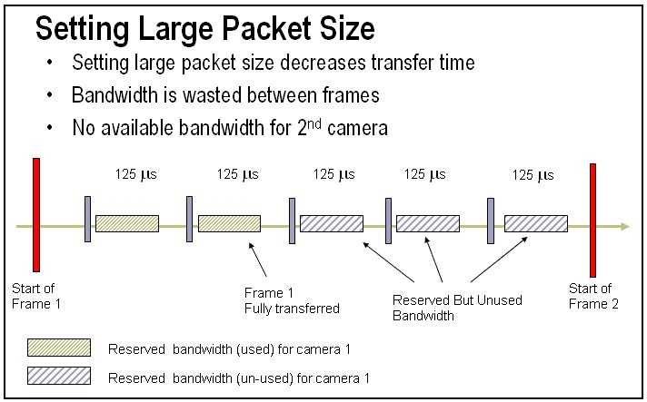
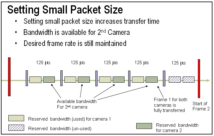
You can speed up the time it takes to transfer an image from the camera to the host. This is done by increasing the packet size. But then there is less room within each slice of isochronous transfer to allow for other cameras to send their packets. If your frame rate is low, you can decrease the packet size. This will increase the time it takes to transfer the image, but it will free up some bandwidth to allow more devices to send their packet with in the 125 microsecond time slice. Compare the 2 figures below. In the first figure, Camera 1 has reserved a large amount of bandwidth and will transfer its full image within 250 microseconds. But by setting up a large packet size, there is not enough remaining bandwidth for a second camera.
In the next figure, Camera 1 has cut its packet size in half. By doing this, it increases the frame transfer time to 500 microseconds, but still maintains its overall frame rate. It also frees up enough bandwidth to add a second camera. In this scenario, both cameras have the same amount of data that need to be transferred over the IEEE 1394 bus.
Another thing to consider when using multiple cameras is the power consumption of each camera. If the cameras are powered by the PCI bus, there will not be enough power available to provide many cameras what they require. It is recommended to use a hub with external power in order to expand your IEEE 1394 ports to use multiple cameras. Typical cameras will require 3 to 5 Watts of power. If cameras are not detected by the host computer, it is an indication that there is not enough power provided to all of the cameras.
Formats:
- Format 0: VGA non-compressed (MAX 640x480)
- Format 1: Super VGA non-compressed (Max 1024x768)
- Format 2: Super VGA non-compressed (Max 1600x1200)
- Format 3,4,5: Reserved
- Format 6: Still image storage
- Format 7: Camera specific format
Each format also includes different modes such as YUV 4:4:4, RGB, Mono 8, etc. The 4:4:4 refers to the amount of compression that takes place on each of the 3 color planes. A value of 4 for each indicates that no compression has been applied and each color plane uses 1 byte to represent its data. A value of 2 in any spot indicates that the corresponding color plane has been compressed into 4 bits, or half of the non-compressed color plane.
NI-IMAQdx
NI-IMAQdx is hardware driver provided by NI that handles the low level interfacing with the IEEE 1394 bus. It comes with LabVIEW VIs, plug in support for Vision Assistant and Vision Builder AI, and API support for LabWindows/CVI and Microsoft Visual Studio. It also installs needed support files to configure cameras connected to the Compact Vision System. After installation, you can go to Measurement & Automation Explorer to configure your IEEE 1394 camera. The driver also ships with many example programs for each Application Development Environment to help users immediately begin acquisition with their IEEE 1394 camera. NI-IMAQdx also installs support for the Legacy NI-IMAQ for IEEE 1394 driver
NI-IMAQdx is part of the Vision Acquisition Software package and can be purchased from ni.com.
Hardware Options
There are 2 hardware options when using NI-IMAQdx to acquire from IEEE 1394 cameras. You can use the NI 145x Compact Vision System or you also can use a IEEE 1394 board that plugs into your PC. You can either use an NI Frame Grabber Device or a third-party board.
NI provides a range of machine vision hardware for easy connection with NI Compact Vision Systems or NI IEEE 1394 interface devices.
Installing, Configuring and Using Your Camera
Installation:
Refer to the your hardware documentation to install and configure your hardware. If you are using the Compact Vision System, refer to the Quick Start Guide that is shipped with the device and the NI 1450 User Manual which is installed in your programs folder (Start>>Programs>>National Instruments>>Vision>>Documentation>>NI 1450 User Manual).
After installing and configuring your hardware follow these steps to configure your IEEE 1394 camera:
1. Launch Measurement & Automation Explorer (MAX) and press F5 to refresh its screen.
2. In the MAX configuration tree, click the plus sign next to the Devices and Interfaces folder. If you are using the Compact Vision System, it will show up under Remote Systems. If you are using a IEEE 1394 Device that is plugged into your Computer, it will show up under My System.
3. Click the plus sign next to the IMAQdx Devices folder to view a list of cameras that are connected to your IEEE 1394 Device.
Note: If you'd like to use the Legacy NI-IMAQ for IEEE 1394, you can right-click on your device (your camera) and specify which driver to use. With the a CVS your camera will show up in both categories automatically.
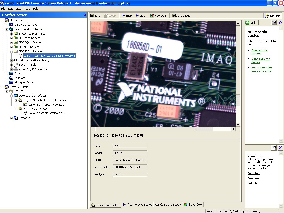
4. At the top of the display in MAX you can click on the Snap button to acquire a single image and display it in the window, or you can click on the Grab button to acquire and view continuously. You can also view a histogram of the image or save it to disk.
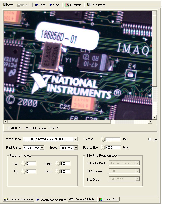
5. You will see 4 tabs at the bottom of the MAX Window. All 4of these tabs are populated with options that the IMAQ driver reads directly from the camera itself. You can modify some of the values, but the options are defined by the camera vendor. The Camera Information tab is displayed in the image above and contains information about the camera. The Acquisition Attributes tab shown below allows you to select the Video Modes and Time-out. If you are using Format 7 (explained below), you can also modify the Packet Size and Region of Interest.
Note: With the NI Compact Vision System you can modify the Region of Interest even if you are using Formats other than Format 7. This does not change the amount of data that is transferred over the bus. It only changes the amount of data your Application Software will read into memory. Using Format 7 with the Compact Vision System works the same way as it would with a PC.
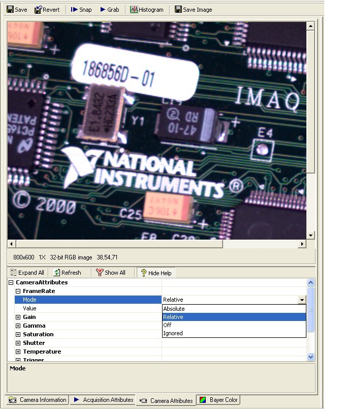
The Camera Attributes Tab shown below allows you to select different options for your camera such as Brightness and Gain.
The fourth tab, Bayer Color, is available for cameras that output the image in Bayer format. In this case a grid of filters is layed over the sensor so each pixel senses only one color. The value of the other two colors is determined by interpolating the color values of adjacent pixels. The following document describes Bayer patterns in further detail
6. When the settings of your camera are where you want them, click on the save button at the top of the display in MAX.
7. Close MAX
Configuring Format 7:
When using other formats, the packet size, frame rate, and Region of Interest are fixed depending on the mode that you use within that format. But with format 7, you can modify either the packet size or the Region of Interest to control the amount of bandwidth that will be reserved by the camera and thus controlling the maximum frame rate. View the image above that displays the Video tab in MAX. This is the tab where you select the following items for Format 7.
1. Select Format 7 for the Video Mode.
2. Select the Desired Region of Interest
3. Select the Packet Size
Even though you can modify the Packet Size in Format 7, you can still only choose discrete values that are predetermined by the camera manufacturer. MAX will automatically coerce the value for the Packet Size to its nearest valid value and display the result for you. The resulting maximum frame rate in frames/second can be calculated by the following equation: (Packet Size in Bytes * 8000) / (width*height*pixel byte depth).
Note: some cameras may require that you trigger the camera when using it in Format 7 mode
Programming:
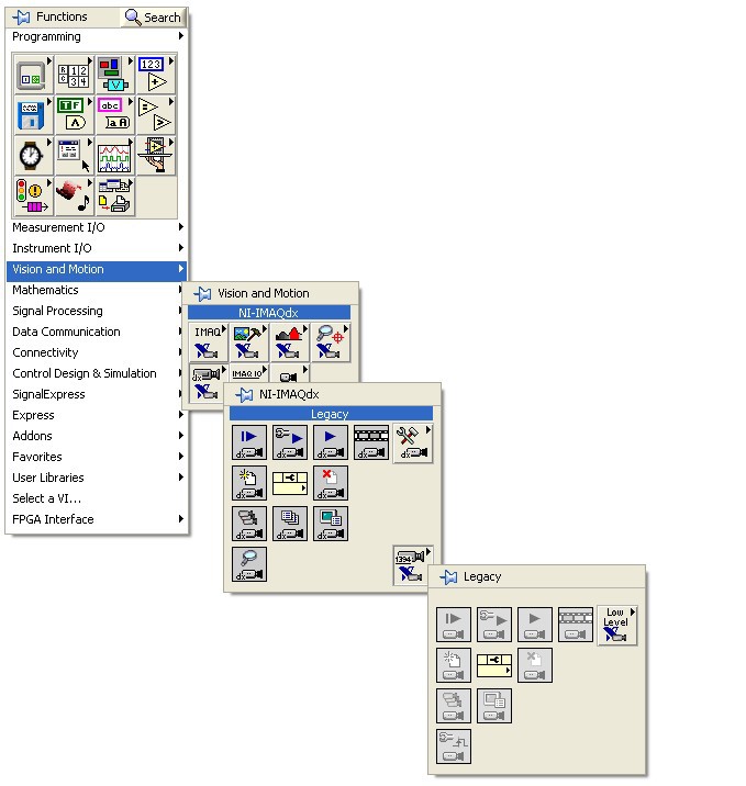
The NI-IMAQdx driver will install the User Manual and a Function Reference Manual that you can access from the Start Menu in Windows. If you are using LabVIEW, it will also install a specific palette of VIs that can be used to program the acquisition from IEEE 1394 Cameras. The palette is titled IMAQdx. It includes Configuration, High Level VIs, Low Level VIs, Triggering, and access to the registers on the IEEE 1394 Camera.
Within the IMAQdx palette is a subpalette for Legacy NI-IMAQ for IEEE 1394. IMAQdx is the latest and most complete driver and should be used for any new development. The legacy drivers and function calls are available for any previously written programs that may require them. They also appear dimmed to stress the use of the IMAQdx function calls instead.
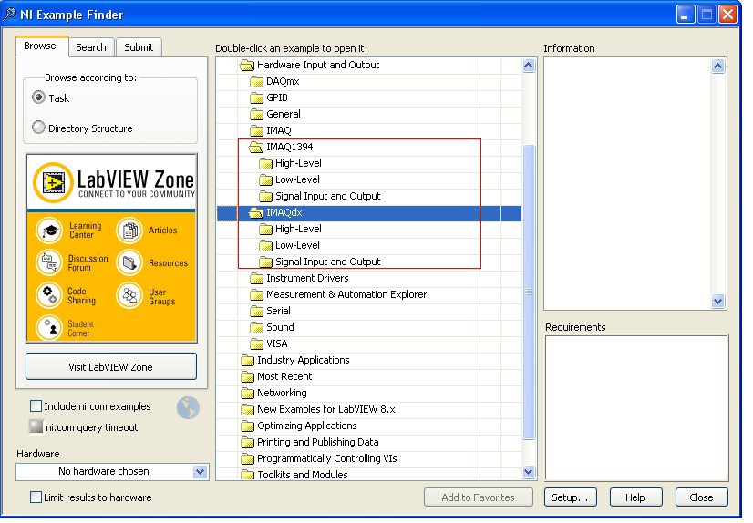
NI-IMAQdx will also install a variety of example programs that demonstrate how to write your VI to do Snaps, Grabs, Sequences, Triggers and more. In LabVIEW, these can be accessed by going to Help>>Find Examples which will bring up the NI Example Finder, as shown below. When browsing Hardware Input and Output, there are separate folders for IMAQdx and Legacy NI-IMAQ for IEEE 1394.
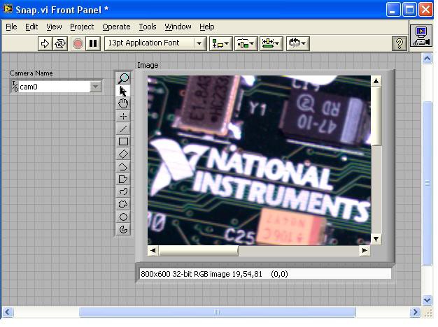
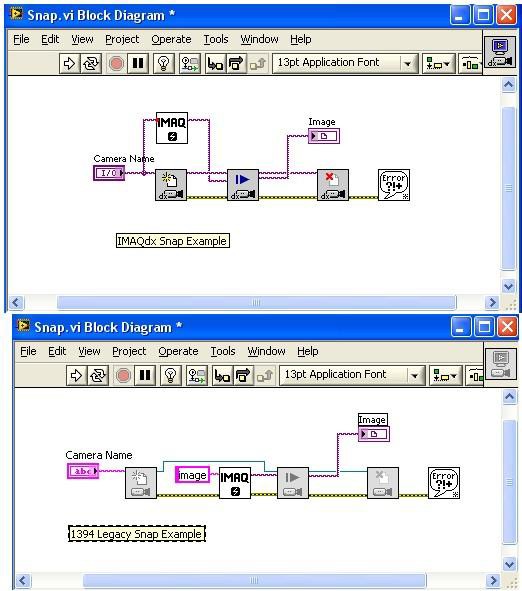
The following Front Panel and Block Diagram illustrate how to perform a snap of your IEEE 1394 camera in LabVIEW . This example uses the Image Display Control available for versions of IMAQ later than 2.6.0.
Front Panel:
Block Diagram:
The Driver also installs example programs that demonstrate how to program acquisitions in CVI, Visual Basic and C. You can use the User Manual and Function Reference Manual to find detailed descriptions of how to make calls into the NI-IMAQdx Driver.
Note: you can also find many useful example programs on-line at ni.com that include all applicable programming environments.
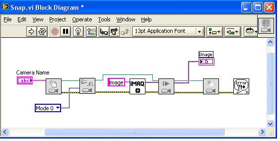
Triggering:
Some DCAM compliant IEEE 1394 cameras support triggering. This aspect has changed from previous versions of NI-IMAQ for IEEE 1394. The following Block Diagram is for the Legacy Driver and is the easiest way to demonstrate the concept. This program is the same as the previous snap example program with one VI added to it, the IMAQ1394 Configure Trigger.vi. If programming in CVI, Visual Basic or C, you would use the IMAQ1394ConfigureTrigger function. This function will send an isochronous command to the camera to tell it to expect a signal on its external connector.
This example uses Mode 0 for the camera mode. There are 4 different modes of triggering that are specified by the DCAM specification. Cameras are not required to support all of these.
- Mode 0: The camera starts integration from the external trigger input falling edge. Integration time is described with the "shutter" attribute.
- Mode 1: The camera starts integration from the external trigger input falling edge. Integration time is equal to low state of the external trigger.
- Mode 2: The camera starts integration from the first external trigger input falling edge. At the Nth external trigger input falling edge, integration will be stopped. (N defined by the parameter control.)
- Mode 3: This is the internal trigger mode. The camera will issue a trigger internally. The cycle time is N (parameter) times of the cycle time of fastest frame rate. The integration time is specified with the "shutter" attribute.
- You may also choose to disable the trigger and the camera will start integrating immediately.
If using Mode 0 through 4, there must be an external digital signal connected directly to the camera. If using a 3rd party IEEE 1394 plugin device, the user must provide this digital signal. If using the CVS, the user may use the digital I/O port to control the timing of the signal connected to the camera. Also, NI Digital Data Acquisition Devices may be used to generate the trigger.
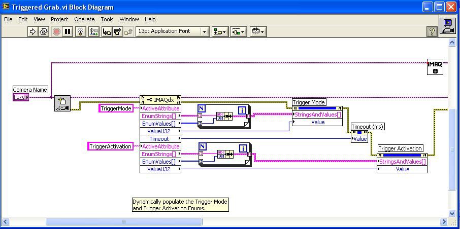
For IMAQdx the triggering functions are controlled using property nodes, as shown in the block diagram below. Please refer to Triggered Grab.vi, an IMAQdx example program (available by searching the NI Example Finder) for further information.