Application Design Patterns: State Machines
Overview
The State Machine is one of the fundamental architectures LabVIEW developers frequently use to build applications quickly. State Machine architecture can be used to implement complex decision-making algorithms represented by state diagrams or flow charts. A state machine can be implemented using innate LabVIEW functions; no additional toolkits or modules are required for the architecture.
This article walks through what a state machine is, example use cases, some conceptual examples of a state machine, and walking through code example of a state machine.
Contents
- What Is A State Machine?
- Why Use a State Machine?
- Creating a State Machine
- State Machine Example Program
- Creating Your Own State Machine Application
- Next Steps
What Is A State Machine?
A state machine is a programming architecture that allows dynamic flow to states depending on values from previous states or user inputs.
This architecture is suitable for applications that can be described as a combination of:
- States
- Decision-making logic that determines when to move to a particular state
A state can be defined as the status within the program while accomplishing the overall task of the program; examples of states may be initializing, waiting, running a calculation, checking status, etc.
Logical statement help determine when to move to a new state and what state to move to. Events can be used to trigger moving from one state to the next; these can be programmatic events or user-defined, like pressing a button.
Each state in a State Machine does something unique and calls other states. State communication depends on some condition or sequence. To translate the state diagram into a LabVIEW programming architecture, you need the following infrastructure:
- While Loop – continually executes the various states
- Case Structure – each case contains code to be executed for each state
- Shift Register – contains state transition information
- Transition code – determines the next state in the sequence (see Transition Code Examples section below)
Why Use a State Machine?
State Machines are used in applications where distinguishable states exist. Each state can lead to one or multiple states and can also end the process flow. A State Machine relies on user input or in-state calculation to determine which state to go to next. Many applications require an “initialize” state, followed by a default state where many different actions can be performed. The actions performed can depend on previous and current inputs as well as states. A “shutdown” state can then be used to perform clean up actions.
Besides its powerful ability to implement decision-making algorithms, state machines are also functional forms of application planning. As the complexity of applications grow, so does the need for adequate design. State diagrams and flowcharts are useful and sometimes essential for the design process. Not only are State Machines advantageous in application planning, they are also easy to create.
Use Cases
For example, the following applications can benefit from the state machine pattern:
- Single-page or tabbed dialog boxes. Each tab of the dialog box corresponds to a state. A user initiates state transitions by clicking a particular tab. For each tab, any actions the user can perform are included in the state.
- An automated teller machine (ATM). The states in this application might include waiting for user input, checking the requested amount against the account balance, dispensing the money, printing the receipt, and so on.
- An application that takes one measurement, logs it to disk, and then waits for another user action. The states in this application might include waiting for user input, performing the measurement, logging the data, displaying the data, and so on.
- State Machines are most commonly used when programming user interfaces. When creating a user interface, different user actions send the user interface into different processing segments. Each of these segments will act as states in the State Machine. These segments can either lead to another segment for further processing or wait for another user event. In this example, the State Machine constantly monitors the user for the next action to take.
- Process testing is another common application of State Machines. In this example, each segment of the process is represented by a state. Depending on the result of each state’s test, a different state may be called. This can happen continually, performing in-depth analysis of the process being tested.
There is another design pattern that can be used to implement a user interface, the Queued Message Handler. A Queued Message Handler is a more sophisticated version of the State Machine and offers additional flexibility, but it also adds additional complexity.
Creating a State Machine
Creating an effective State Machine requires the designer to (1) make a list of possible states. With this list, the designer can (2) plan how each state is related to another. Then, the state diagram can (3) be translated to LabVIEW graphical programming architecture.
Example: Firing a Cannon
In this example, we want to generate an application that fires a cannon continuously without allowing it to get dangerously hot.
(1) List Possible States
To begin, we make a list of all possible states for our task. To accomplish the task of continuously fire the cannon will need to:
- Initialize the program
- Power on the cannon
- Fire the cannons
- Check the device temperature (status)
- Cool the device passively (if the temperature is still within range but increasing)
- Cool the device actively (if the temperature is out of range)
- Shut down device
(2) Map States’ Relationships in a State Diagram
Next, we will consider how these states are related to each other and create a state diagram. When creating the state diagram, consider what would cause the program to move from one stat to the next – is it an automatic transition? Is there an external trigger from the user? Is the transition based on the outcome of a calculation?
For example, let’s consider the relationships between the initialization state and other states.
- Initialization is the first step in the program. There will be no inputs for this state.
- Once initialized, if no errors are present, we will move on to power on the cannon.
- If errors exist, shut down the program
- If the user presses a stop button during initialization, we want to move to the shutdown state.
Notice that while thinking through how states relate to one another, we have started to define the logic for moving between these states. The programming logic that we will use in code depends on (1) the number of possible transition states, and (2) the number of inputs being considered in the logic. Options for code transition are discussed below in the Transition Code Examples section.
Continue working through how the states relate to one another until you have a full state diagram. The state diagram will include all states and the relationship between them (Figure 1). Notice that in this diagram, the states (oval nodes) describe the actions that are performed when the control process is in that state, whereas the transitions (arrows) simply describe when and how the process can move from one state to another.
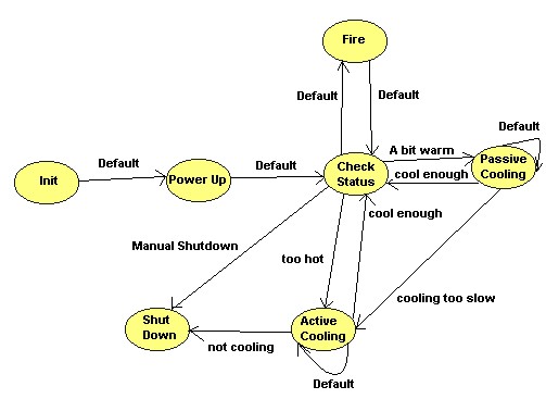
Figure 1: State Diagram of Firing a Cannon
The relationship between each state will help you in programming the logic needed to move from one state to the next.
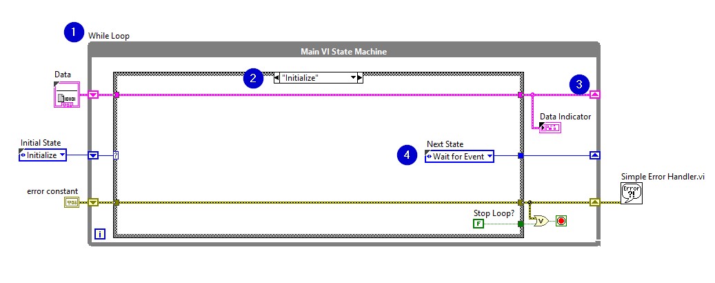
(3) Build a State Machine in LabVIEW
After defining the states and their relationship in a state diagram, you can translate this to coding architecture in LabVIEW (Figure 2). The flow between states of the state diagram (Figure1) is implemented by the loop. The individual states are replaced by cases in the case structure. Each state in the diagram above corresponds to a subdiagram of the Case Structure. Each state:
- Performs some action
- Tells the state machine what the next state is by passing an instruction to a shift register on the While Loop (i.e. transition code)
A shift register on the while loop keeps track of the current state, which is fed into the case structure input.
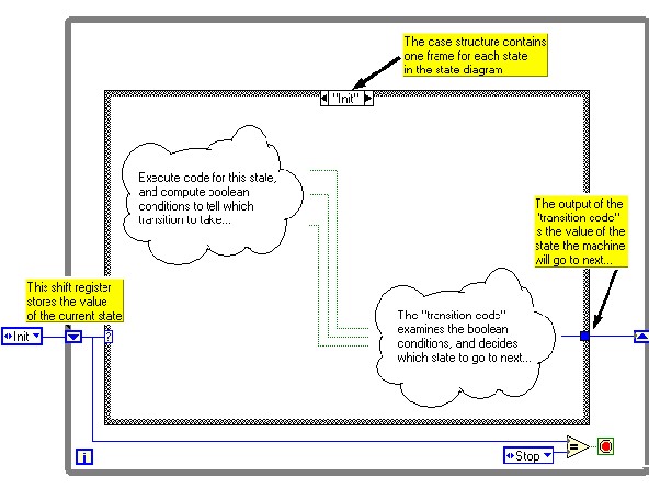
Figure 2: State Machine
State Machine Example Program
Refer to the Single Shot Measurement sample project, available from the Create Project dialog box, for an example of adapting this template to a measurement application.
- After initialization, the state machine transitions to the Wait for Event state. This state contains an Event structure that waits for front panel changes. When a user clicks a button, LabVIEW recognizes the event and switches to the appropriate subdiagram of the Event structure. This subdiagram initiates a transition to the appropriate state.
- Each state has access to a cluster of data. The data types in this cluster are defined in Data.ctl.
- The valid states are listed in State.ctl, which is a typedef. Using a typedef for state transitions restricts the transitions you can use, reducing the chances that the state machine gets into an unrecognized state.
- Only the Stop state can stop the application. This design prevents accidental and partial shutdowns by guaranteeing that:
1. Shutdown code runs only when the user wants to stop the application.
2. Shutdown code always runs to completion.
- Only one state executes at a time, and the single While Loop means all tasks execute at a single rate. If you need multi-rate or parallel tasks, consider the Queued Message Handler or Actor Framework templates, available from the Create Project dialog box.
- The Wait for Event state is the only one that recognizes user input. The state machine must be in this state for any user input to be accepted.
Creating Your Own State Machine Application
Consult the Modify the Simple State Machine LabVIEW Template tutorial for how to get started with.
Determining Your Needs
Before you customize the template, ask yourself the following questions:
- What states does the application consist of? The answer to this question determines the states you add.
- For each state, what should the next state be? The answer to this question determines the value of the Next State enum that each state sends to the shift register on the While Loop.
A single state can conditionally transfer to multiple states. An example is the Wait for Event state in the template, which transitions to a state based on user input. - What kind of data will each state need access to? The answer to this question determines what data types you add to Data.ctl.
- What are some errors that could occur, and how should the application respond to these errors? The answers to these questions determine the amount of error handling you need.
Transition Code Examples
There are different methods to determine which state to transition to next, discussed below.
Note that while the examples images show the “Init” state, these transition possibilities could apply to any state.
One-to-one: If you always transition from State A to State B, there is no need to program any logic, just output the name of the next case (Case B) of to the shift register.
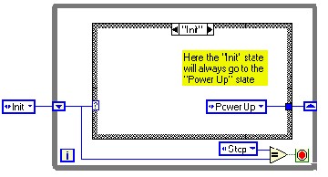
Figure 3a: Only One Possible Transition State
One-to-two: If you could transition from State A to State B or State C, you can use a Select function to assess the status of an indicator. You should assess something that determines which State you want to move to. For example, in Figure 3b we see that the user input of the Stop Button determines whether we move from the Power Up state or proceed to Shut Down.
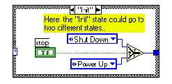
Figure 3b: Two Possible Transition States
One-to-multiple using Arrays: If you have multiple states that you could transition to, you could use a Boolean area associated with an enum constant to program the transition. For example, in Figure 3c, some code is conducted where the outcome of the code determines the transition, the output of which is an array of Booleans. The Boolean array correlates with an Enum constant which contains a list of possible states that could be transitioned to. Using the Index Array function, the index of the first “True” Boolean in the Boolean array is output. Then, using the Array Subset function, you can pull out the appropriate from the Enum constant it correlates with.
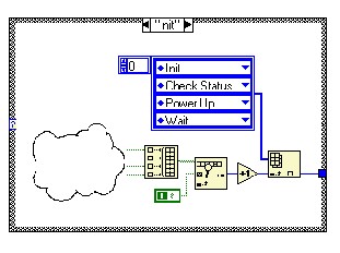
Figure 3c
Tip: Recall that arrays are 0-indexed and Enums are 1-indexed. To correlate the Boolean Array with the Enum constant, use the Increment function to correct that offset.
One-to-multiple using While Loop: Another option if you have multiple possible transition states is to use a while loop inside of a case. The code inside of the while loop will continue until a Boolean status is set to true, triggering the stop button. This will effectively allow code to run until a triggering event occurs.
Figure 3d demonstrates an “Init” state using an inner loop and case structure to transition to the next state. The inner case structure contains one diagram for each transition that leaves the current state. Each of the cases in the inner case structure has two outputs – a Boolean value, which specifies whether or not the transition should be taken, and an enumerated constant, which specifies the state to which the transition goes. By using the loop index as an input to the case structure, this code effectively runs through each transition case one by one, until it finds a diagram with a “True” Boolean output. After the “True” Boolean output is found, the case outputs the new state to which the transition goes. Though this method may appear slightly more complicated than the previous methods, it does offer the ability to add names to transitions by “casting” the output of the loop index to an enumerated type. This benefit allows you to add “automatic documentation” to your transition code.
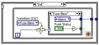
Figure 3d
Other Programming Considerations
Code Redundancy
Problem: The hardest part of creating a State Machine is to differentiate between possible states in the state diagram. For example, in the Coke Machine state diagram (Fig.4), we could have had 0, 5, 10, 15, 20, 25, 30, 35, 40, 45, 50 cent states rather than having a “wait for response” state that goes from one state to another depending on which type of coin is dropped. That would create 11 different states with the exact same case diagram. Redundant code can create a big problem in a larger application.
Solution: If different states have the same case diagram, try to combine them into one state. For example, the “wait for response” state is created to avoid code redundancy.
Enum use
Problem: Enums are widely used as case selectors in State Machines. If the user attempts to add or delete a state from this enum, the remaining connected wires to the copies of this enum will break. This is one of the most common obstacles when implementing State Machines with enums.
Solution: Two possible solutions to this problem are:
1. If all the enums are copied from the changed enum, the breaks will disappear.
2. Create a new control with the enum, and select “typedef” from the submenu. By selecting typedef, all of the enum copies will be automatically updated if user adds or removes a state.
Next Steps
If you are interested in learning more about State Machines and other advanced architectures in LabVIEW, consider taking the LabVIEW Core 2 customer education course.