Command-based Communication Design Pattern Using Simple Messaging (STM)
Overview
This document provides a design pattern for command-based network communication that uses the Simple Messaging (STM) protocol as a foundation.
Contents
- Background
- Overview
- Client Application - Implementation Overview
- Command/Parameter Sender (Client Application)
- Data Receiver (Client Application)
- Server Application - Implementation Overview
- Command Parser (Server Application)
- Medium Priority Tasks (Server Application)
- High Priority Task (Server Application)
- Conclusion
Background
It is common for embedded applications to operate in a headless configuration, performing specific actions in response to commands coming from a remote host. Frequently, the embedded application communicates with the host via networking protocols such as TCP or UDP.
Distributed applications generally operate within a system architecture based on events, where the server responds to commands sent by the client. Typical communication requirements include:
- A modular framework that supports software maintenance and expansion
- Optimized data transfer - Information should be transferred across the network only when new data is available
- Ability to 'command' the server to transition between different operating modes
- Ability to 'command' the server to process data generated by high priority tasks
- Access to the high priority task data for processing or logging on the server
This document describes a design pattern for implementing command-based communication in a LabVIEW Real-Time application, intended to illustrate these general concepts.
You can install the Simple Messaging (STM) library and command-based communication example code directly from VI Package Manager. If you are not familiar with the
Overview
Command-based communication has two participants: the client application and the server application. The client application typically runs on a MS Windows host PC. It sends commands and parameters to the server and receives data and status information sent by the server.
The server typically runs on an embedded target such as LabVIEW Real-Time, and executes deterministic tasks based on commands received from the client.
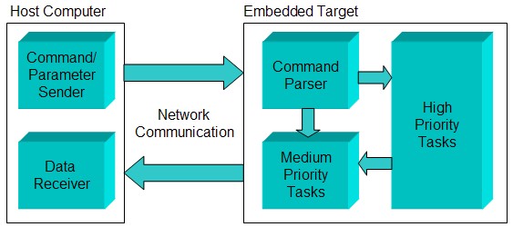
Figure 1. Command-based communication block diagram
The block diagram shown in Figure 1 illustrates the organization of the command-based design pattern. By following this application structure you will create scalable software applications that are compatible with most LabVIEW embedded targets.
To better illustrate the implementation, this document uses an example server application with the following functionality:
- Generate a simulated sine wave in the embedded server at a frequency specified by the remote client
- Calculate the power spectrum on the generated signal without disturbing the deterministic data generation
- Apply a power spectrum window that is controlled by the user from a remote client.
- Transmit the original and processed data to the client
Client Application - Implementation Overview
The server application is headless, so user-driven actions must be initiated at the client and communicated to the server via commands. The client also receives data coming from the server for display.
The client application has the following parts:
- Command/Parameter Sender loop
- Data Receiver loop
In general, the command/parameter sender loop actions can be driven by any source. In the example program, commands are originated by the user interface (UI). Each front panel control is linked to one or more commands that perform specific operations on the server. The following figure shows the example application front panel.
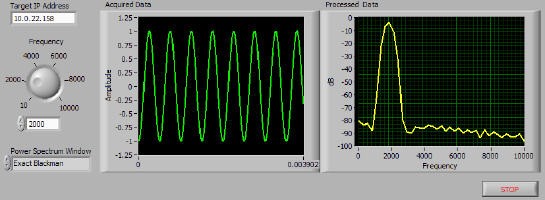
Figure 2. Client application example front panel
Figure 3 shows a high level view of the host application implementation.
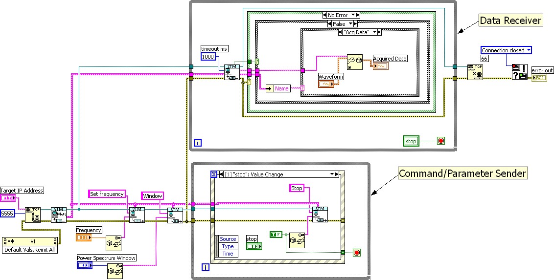
Figure 3. Example client application LabVIEW diagram
The following sections describe the implementation of each of the components in more detail.
Command/Parameter Sender (Client Application)
The Command/Parameter Sender loop is the counterpart of the Command Parser in the server application. It responds to UI events and sends the appropriate commands to the server. The following figure and comments describe the implementation of this loop.
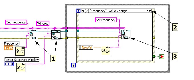
Figure 4. Example client application Command/Parameter Sender loop
1. Initialize server parameters. It is a good practice to initialize all server parameters when starting the application. If they are not initialized there is a good chance that they will be out of synch with the client. Keep in mind that the client application does not send any parameter values unless there is a user interface event. This means that the value of that parameter in the server is unknown until the user modifies the corresponding value on the client panel. To avoid this situation, the client application should initialize all parameter values on the server by sending data to them before entering the event loop.
2. Wait for UI events. The client application is designed to run on a platform that supports UI events. The most efficient approach is to use the LabVIEW Event Structure, which sleeps until there is user interface activity. No CPU time is used when there are no commands to handle. This approach also makes the design pattern easy to expand. If additional commands are needed, just add the controls to the Front Panel and add the corresponding event case to handle the action.
3. Send command and parameters to the server. The STM Write Msg VI is part of the Simple TCP/IP Messaging API. The example uses it to send user commands to the server. On the receiving side, the server's Command Parser will interpret the command and pass the data to the appropriate location in the server software.
For ease of maintenance, we recommend that you create an abstraction between user requests and commands sent to the server. This makes the code more modular and hides the implementation details of the server application from the user. For example, the user interface may have a control labeled "Start". "Start" may involve initializing hardware, initializing logging parameters, setting triggers and initiating an acquisition. The user doesn't need to know what "Start" does under the hood – it just "Starts" the application. With this approach, you don't have to relate every control on the Front Panel to a specific command.
The following figure demonstrates an implementation of this type of abstraction. The benefit is that for the user, only one action was taken, but in reality, the client sent several commands to the server. Having distinct commands for specific actions helps maintain, scale and reuse the application code.
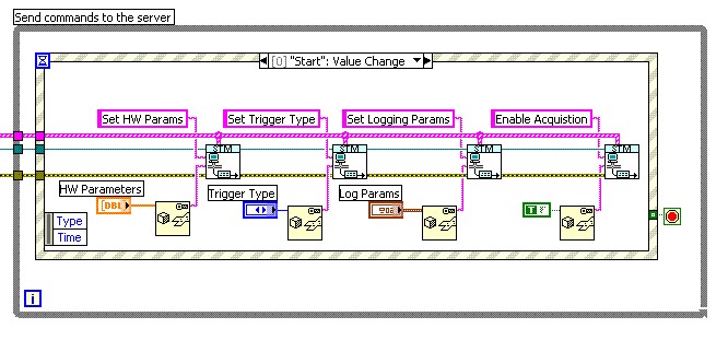
Figure 5. Translating UI Events to server commands
Data Receiver (Client Application)
The Data Receiver loop is responsible for receiving and processing each incoming message from the server. In this example, the Data Receiver simply displays the data. Processing may involve logging to disk, performing some analysis, etc. The frequency of incoming packets is usually much higher than in the Command Parser, because the sending of commands is sporadic as opposed to the continuous data stream typically generated by the server.
In this situation, your client application must receive and process packets at high rates. Ideally, packet processing should always be completed in time to go back and retrieve the next packet. If heavy processing is required and your application does not always keep up, it may be necessary to send the data to asynchronous loops that handle each particular operation. Queues are a good mechanism to buffer and transfer data to parallel loops.
In complex applications, the Data Receiver may send commands to the server directly. For example, the server might be constantly sending status and error information. The Data Receiver must make sense of this information and take action in case an error occurs. Taking action might involve sending commands to the server to shut down the acquisition, close all hardware references and shut down the system.
The following figure shows the implementation of the Data Receiver loop in our example application.
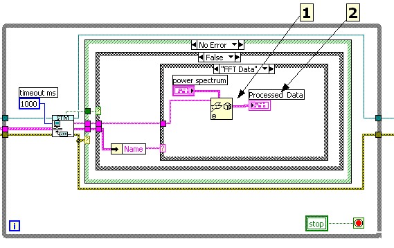
Figure 6. Example client application Data Receiver loop
1. Convert the incoming data to the appropriate type. Notice that the Data Receiver loop must know how to interpret each incoming packet of data. In this particular example, the server sends a waveform data type with the “Acq Data” message. Upon receiving the flattened waveform data, the Data Receiver must restore it using the Unflatten from String VI using a waveform conversion type.
2. Display/Process data. Once the data is received, the Data Receiver loop should process it accordingly. Remember that the display/processing must be able to keep up with the speed of the incoming packets.
Server Application - Implementation Overview
The server application runs a LabVIEW Real-Time application. It has no user interface and only performs operations commanded by the client.
The server application has the following design pattern elements:
- Command Parser
- Medium Priority Task(s)
- High Priority Task
The following figure shows an overall view of the example server block diagram. Notice that each of the main elements is encapsulated in its own loop.
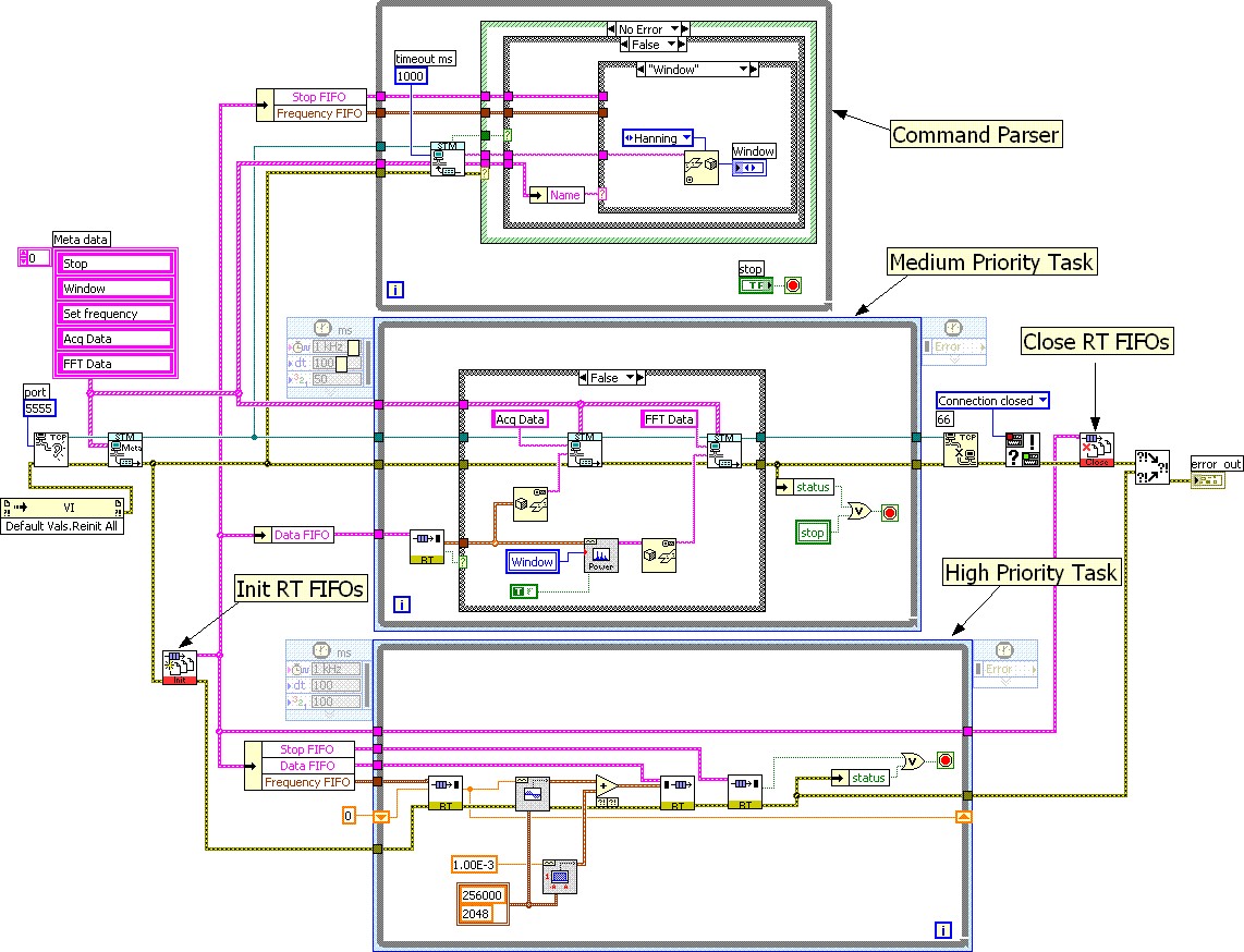
Figure 7. Example server application LabVIEW diagram
The following sections describe the implementation of each of these components in more detail.
Command Parser (Server Application)
The command parser waits for commands coming from the client, interprets them and routes the incoming command parameters to the appropriate loop. Figure 8 shows the example server command parser loop in greater detail.
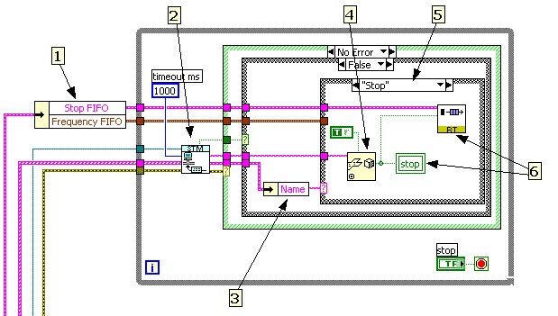
Figure 8. Example server application Command Parser loop
The following paragraphs explain the command parser operation. Note that it’s operation is similar to the client Data Receiver loop.
1. Retrieve the RT FIFO references that are relevant to the command parser. To keep the code organized, it is a good idea to wrap RT FIFO initialization and clearing operations in subVIs. Since the application may use numerous RT FIFOs, it is convenient to bundle them as clusters so that each FIFO reference can be extracted as needed. In this particular example, the Command Parser Loop needs to communicate 2 types of information to the Time Critical loop (Stop and Frequency information), hence the need for 2 RT FIFOs.
2. Read incoming commands from the client. The STM Read Msg VI is part of the Simple TCP/IP Messaging API. An important feature of this VI is the timeout parameter. By default it is set to timeout every 25 seconds. This feature allows the loop to sleep until a new command needs processing. This is very efficient since the Command Parser loop will consume very little CPU time if there are no commands to process.
3. Retrieve the name of the incoming command. Refer to the Simple TCP/IP Messaging Protocol document for more details.
4. Convert the incoming data to the appropriate type. It is the developer's responsibility to know the expected data type for each command. The data can be of any type recognized by LabVIEW (integer, floating, complex, boolean, a cluster, an image, etc.).
5. Select the command handler. This is implemented as a case selector with a separate case for each command supported by the server. This design pattern is very scalable, because new commands are implemented by simply adding a new case. The example Command Parser has cases to handle the following commands: Set Frequency, Window and Stop.
6. Route incoming command data to the appropriate loop. When a command is received, the Command Parser must send the data either to the High Priority Task, Medium Priority Task(s) or both, as shown in Figure 8. To ensure determinism, follow the rules of a typical LabVIEW Real-Time application such as using RT FIFOs for sharing data between high and low priority loops. Communication with medium-priority tasks can be implemented via any other means of communication (deterministic and non-deterministic), including Local and Global Variables, Functional Global Variables, Queues, Notifiers, Occurrences, etc. In general, no other actions should be taken inside the Command Parser. Restricting this loop to data distribution makes the server application very responsive to client commands.
Medium Priority Tasks (Server Application)
In general, a deterministic application has a primary (deterministic) task that preempts all others. Medium priority tasks are operations that run while the deterministic task is sleeping. Examples of Medium Priority tasks include signal processing, sending data to the client via TCP/IP or logging data to disk. Since Medium Priority tasks and the CommandParser are not deterministic, you can use various methods of data sharing between them, such as Queues, Local Variables, Functional Globals, etc. Medium Priority tasks have well defined behavioral states that the client can be toggled by sending an appropriate command via the command parser.
In our example application, performing signal processing and sending data to the client are considered medium priority tasks. Notice that when the client issues a command to change the Power Spectrum Window, the Command Parser can use a non-deterministic method (such as local variable) to route the data to the Medium Priority Task loop, because neither process is deterministic. The following figure shows the implementation of the Medium Priority task loop for the example server.
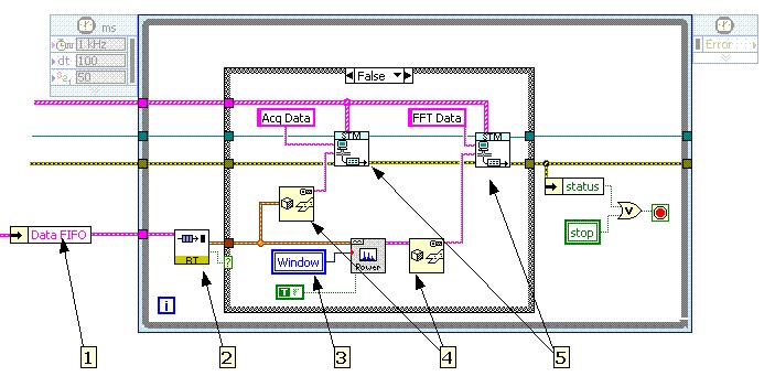
Figure 9. Example server application Medium Priority Tasks loop
1. Retrieve the RT FIFO references that are needed in this loop.
2. Retrieve data from the high priority task. Note that the FIFO 'empty' output is wired to a case structure to enforce that data processing and transfer occurs only when new data is available. This allows the medium and high priority loops to run asynchronously while avoiding situations where invalid data is send to the client.
3. Read the current setting for the "Window" parameter. This setting came from the client, via the Command Parser. Since the Command Parser is also running asynchronously, parameter changes from the client go into effect during the next iteration of this loop.
4. Flatten data to a string for transmission to the client. See the Simple TCP/IP Messaging protocol document for more information.
5. Send data to the client. The STM Write Msg VI is part of the Simple TCP/IP Messaging API. Note that for ease of implementation, this application writes the data as two separate named items; Acq Data and FFT Data. This approach is very expandable. If another data item is required, simply create another Meta data entry and add another instance of the STM Write Msg VI for that data item.
High Priority Task (Server Application)
The High Priority Task loop represents the deterministic part of the application. Typical deterministic tasks include data acquisition, closed-loop control or simulation model execution.
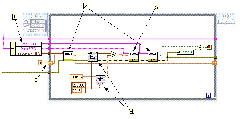
Figure 10. Example server application High Priority Task loop
1. Retrieve the RT FIFO references used in this loop. Notice that this VI receives initialized references for the RT FIFOs. This guarantees that when the time critical code starts running, all the FIFOs are ready to use.
2. Read the client command parameters. Since the Command Parser is running asynchronously to this VI, a value update can happen during an iteration of this loop. The RT FIFO interface ensures that any commanded change coming from the client is received by the time critical loop.
3. Cache client parameter values. This is a very important element of the design pattern. The example application is optimized because the client only sends data/parameters when they change. Because of its asynchronous nature, this loop will typically execute many times without receiving new parameter values from the client. If there is no new data, however, the RT FIFO Read VI returns its default value. If the default value does not provide the correct behavior, the previous value should be stored in a shift register and used as the default RT FIFO value for the next iteration by wiring it to the RT FIFO Read VI “element” control.
4. Generate simulated data. In the example server, these VIs generate simulated data. In a real application, you could substitute calls to a data acquisition driver, a simulation model, a LabVIEW FPGA device, etc. The type of RT FIFO you need depends on the type that your data source returns.
5. Write data out from the high priority task. Send the data to the Medium Priority Task loop, which processes the data according to the application requirements.
Conclusion
The command-based design pattern presented in this document provides a robust, scalable and optimized framework for LabVIEW embedded applications.