From Friday, April 19th (11:00 PM CDT) through Saturday, April 20th (2:00 PM CDT), 2024, ni.com will undergo system upgrades that may result in temporary service interruption.
We appreciate your patience as we improve our online experience.
From Friday, April 19th (11:00 PM CDT) through Saturday, April 20th (2:00 PM CDT), 2024, ni.com will undergo system upgrades that may result in temporary service interruption.
We appreciate your patience as we improve our online experience.
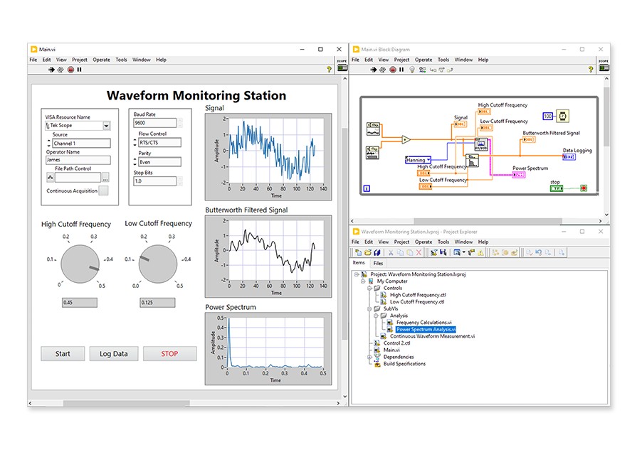
LabVIEW helps you work more quickly. Spend less time developing tests, automating instruments, analyzing data, and generating reports.
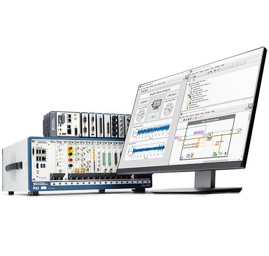
NI offers the hardware, software, and services that help you turn real-world data into insights that drive your business decisions. Choose from products for desktop design and prototyping to fully automated production test systems.
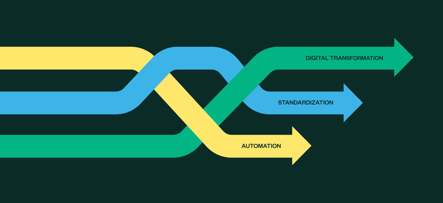
Unlocking the full benefits of test isn’t just about using a better tool. It requires an intentional strategy with automation, standardization, and digital transformation initiatives.