Your Go-To Source for Innovative Solutions
At NI, our automated test and automated measurement systems make breakthroughs possible. Let’s work together to select the right combination of hardware, software, and services so that you’re fully equipped to build the extraordinary.

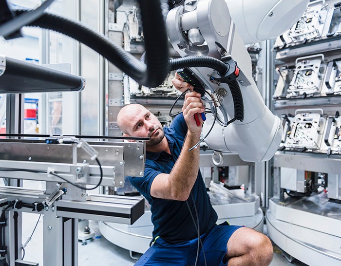
Agile, like you.
Test requirements and market trends are constantly changing. As your needs evolve, so do we. Our systems integrate easily with new technologies and support the latest engineering methods, putting you in position to innovate faster.

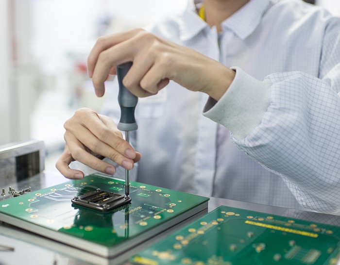
We’re in this together.
When you purchase a product or service from us, you’re not making a one-time transaction. Our industry experts are available if you have questions or need support.
We’re dedicated to you. Period.
02
Keep it real.
We want to know what’s preventing you from reaching your goals. Discuss your obstacles with a solutions specialist.