Digital Multimeter Measurement Fundamentals
Overview
A digital multimeter (DMM) is an electrical test and measurement instrument that can measure voltage, current, and resistance for DC and AC signals. Learn how to correctly use and understand a digital multimeter.
Contents
- DMM Display Digits
- Voltage Measurements with a DMM
- Current Measurements with a DMM
- Resistance Measurements with a DMM
- Additional DMM Measurements
- Noise Rejection Parameters
- DMM Measurement Tips
DMM Display Digits
Digital multimeters (DMMs) can be useful for a variety of measurements. When choosing a DMM or understanding one you are using, the first things to be aware of are the display digits of the instrument.
It is important that a DMM has enough digits to be precise enough for your application. The number of display digits on a DMM is not related to the resolution, but can help determine the number of significant values that can be displayed and read. DMMs are said to have a certain number of digits, such as 3 ½ digits or 3 ¾ digits. A full digit represents a digit that has 10 states, 0 to 9. A fractional digit is the ratio of the maximum value the digit can attain over the number of possible states. For example, a ½ digit has a maximum value of one and has two possible states (0 or 1). A ¾ digit has a maximum value of 3 with four possible states (0, 1, 2, or 3).
Equation 1. DMMs often have fractional digits, which can display only a limited number of states
The fractional digit is the first digit displayed, with the full digits displayed after. For instance, on the 2 V range, the maximum display for a 3 ½ digit DMM is 1.999 V.
Typically, ½ digit displays have full scale voltages of 200 mV, 2 V, 20 V, and 200 V while ¾ digit displays have full scale voltages of 400 mV, 4 V, 40 V, and 400 V.
Voltage Measurements with a DMM
Practically every DMM has a DC and an AC measurement function. Voltage testing is commonly used to test and verify the outputs of instruments, components, or circuits. Voltage is always measured between two points, so two probes are needed. Some DMM connectors and probes are colored; red is intended for the positive point that you want to actually take a measurement of and black is intended for the negative point that is typically a reference or ground. However, voltage is bidirectional, so if you were to switch the positive and negative points, the measured voltage would simply be inverted.
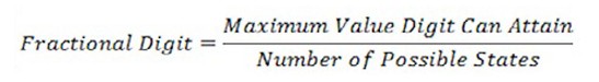
There are usually two different modes for measuring voltage: AC and DC. Typically, DC is denoted with a V with one dashed line and one solid line while AC is denoted with a V with a wave. Be sure to select the correct range and mode for your application.
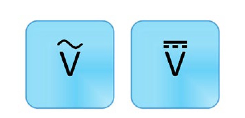
Figure 1. AC voltage (left) and DC voltage (right) measurements are commonly used to test and verify outputs of instruments, components, or circuits.
There are several terms and concepts you should be familiar with when measuring AC or DC voltage.
Input Resistance
An ideal voltmeter has an infinite input resistance so that the instrument does not draw any current from the test circuit. However, in reality, there is always some resistance that affects measurement accuracy. To minimize this problem, a DMM’s voltage measurement subsystems are often designed to have impedances in the 1s to 10s of MΩ. If you are measuring low voltages, even this resistance can be enough to add unacceptable inaccuracies to your measurement. For this reason, lower voltage ranges often have a higher impedance option such as 10 GΩ.
With some DMMs, you can select the input resistance. For most applications, it can be said the higher the impedance, the more accurate the measurement. However, there are a few cases where you might choose the lower impedance. For instance, a conduit that has many different wires inside might have coupling across the wires. Even though the wires are open and floating, the DMM still reads a voltage. The higher impedance isn’t sufficient to eliminate these ghost voltages, but a low impedance provides a path for this built-up charge and allows the DMM to correctly measure 0 V. An example of this at a lower voltage range is if you had traces close together on a circuit.
Crest Factor
When measuring AC signals (voltage or current), the crest factor can be an important parameter when determining accuracy for a specific waveform. The crest factor is the ratio of the peak value to the rms value and is a way to describe waveform shapes. Typically, the crest factor is used for voltages, but can be used for other measurements such as current. It is technically defined as a positive real number, but most often it is specified as a ratio.

Equation 2. The crest factor is a measure of how extreme the peaks are in a waveform
A constant waveform with no peaks has a crest factor of 1 because the peak value and the rms value of the waveform are the same. For a triangle waveform, it has a crest factor of 1.732. Higher crest factors indicate sharper peaks and make it more difficult to get an accurate AC measurement.
Figure 2. The crest factor of an AC signal can affect the accuracy
An AC multimeter that measures using true rms specifies the accuracy based on a sine wave. It indicates, through the crest factor, how much distortion a sine wave can have and still be measured within the stated accuracy. It also includes any additional accuracy error for other waveforms, depending on their crest factor.
For example, if a given DMM has an AC accuracy of 0.03 percent of the reading. You are measuring a triangle waveform, so you need to look up any additional error with a crest factor of 1.732. The DMM specifies that for crest factors between 1 and 2, there is additional error of 0.05 percent of the reading. Your measurement then has an accuracy of 0.03 percent + 0.05 percent for a total of 0.08 percent of the reading. As you can see, the crest factor of a waveform can have a large affect on the accuracy of the measurement.
Null Offset
Most DMMs offer the ability to do a null offset. This is useful for eliminating errors caused by connections and wires when making a DC voltage or resistance measurement. First, you select the correct measurement type and range. Then connect your probes together and wait for a measurement to read. Then select the null offset button. Subsequent readings subtract the null measurement to provide a more accurate reading.
Auto Zero
In addition to performing a null offset, another way to improve voltage and resistance measurement accuracy is by enabling a feature called auto zero. Auto zero is used to compensate for internal instrument offsets. When the feature is enabled, the DMM makes an additional measurement for every measurement you take. This additional measurement is taken between the DMM input and its ground. This value is then subtracted from the measurement taken, thus subtracting any offsets in the measurement path or ADC. Although it can be very helpful in improving the accuracy of the measurement, auto zero can increase the time it takes to perform a measurement.
Current Measurements with a DMM
Another common measurement function is DC and AC current measurements. Although voltage is measured in parallel with the circuit, current is measured in series with the circuit. This means that you need to break the circuit—physically interrupt the flow of current—in order to insert the DMM into the circuit loop to take an accurate measurement. Similar to voltage, current is bidirectional. The notation is similar as well, but with an A symbol instead of a V. The A stands for amperes, the unit of measure for current. Be sure to select the correct range and mode for your application.
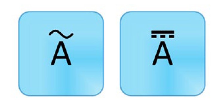
Figure 3. DC current (left) and AC current (right) measurements are helpful for troubleshooting circuits or components.
DMMs have a small resistance at the input terminals, and it measures the voltage. It then uses Ohm’s law to calculate the current. The current is equal to the voltage divided by the resistance. To protect your multimeter, avoid switching out of the current measurement function when currents are flowing through the circuit. You should also be careful not to accidentally measure voltage while in the current measurement mode; this can cause the fuse to blow. If you do accidentally blow the fuse, you can often replace it. See your instrument’s instruction manual for detailed information.
Resistance Measurements with a DMM
Resistance measurements are commonly used to measure resistors or other components such as sensors or speakers. Resistance measuring works by applying a known DC voltage over an unknown resistance in series with a small internal resistance. It measures the test voltage, then calculates the unknown resistance. Because of this, test the device only when it isn’t powered; otherwise, there is already voltage in the circuit and you can get incorrect readings. Also keep in mind that a component should be measured before it is inserted into the circuit; otherwise, you are measuring the resistance of everything connected to the component instead of just the component by itself.
One of the nice things about resistance is that it is nondirectional, meaning if you switch the probes the reading is still the same. The symbol for a resistance measurement is an Ω, which represents the resistance unit of measure. Be sure to select the correct range and mode for your application. If the display reads OL, this means the reading is over the limit or greater than the meter can measure in that range. As discussed earlier, using the null offset can improve your measurement readings.
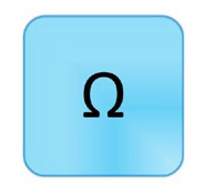
Figure 4. Resistance measurements are commonly used to measure resistors or other components.
Additional DMM Measurements
Many DMMs offer two additional measurement functions: diode testing and continuity testing.
Continuity Testing
Continuity testing helps you identify when two points are electrically connected. This can be very helpful when troubleshooting wire breaks, printed circuit board (PCB) traces, or solder joints. When testing for continuity, it is essential to monitor exactly where the probes are touching. As such, most DMMs emit a sound when they detect a closed circuit, so you don’t have to look up from your probes. As such, the symbol for continuity looks like a sound wave.
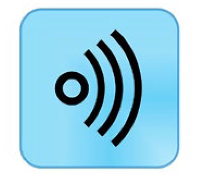
Figure 5. Continuity testing helps you identify when two points are electrically connected.
Continuity testing works just like a resistance measurement; as such, it is essential that your device not be powered when you are testing. It can also be helpful to make sure everything is connected first by brushing the test tips together to verify the beep. If you don’t hear a sound, then check that the probes are firmly connected, your DMM has sufficient battery life, and that you are in the correct mode. You should also look in your user manual to determine the level of resistance required to trigger the sound as it varies from model to model.
If you are testing a circuit that has a large capacitor, you may hear a quick beep and then silence. This is because the voltage the DMM is applying to the circuit is charging up the capacitor and, during that time, the DMM thinks it is a closed circuit when it isn’t really.
Diode Testing
Diode testing displays the forward voltage drop of the diode in volts. The symbol, not surprisingly, is the diode symbol.
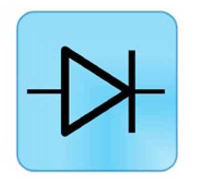
Figure 6. Diode testing displays the forward voltage drop of the diode in volts
The DMM forces a small current through the diode and measures the voltage drop between the two test leads. When measuring a diode, you want the positive probe on the anode side and the negative on the cathode side. The voltage reading typically is about 0.7 V for silicon but can range from 0.5 to 0.9 V and still be a working diode. Germanium diodes are typically around 0.3 V.
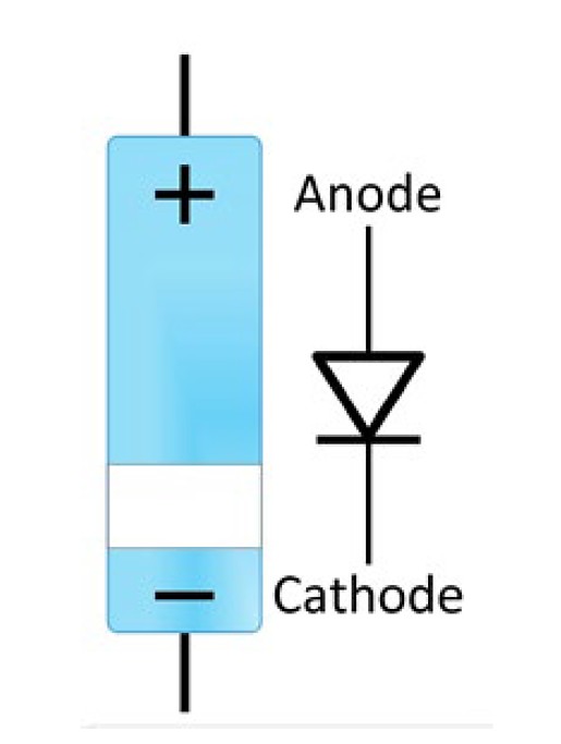
Figure 7. Typically, test a diode with the positive probe on the anode side and the negative on the cathode side. However, switching them can also be illuminating.
Next, switch probes so the negative is on the anode side and the positive is on the cathode side. If the diode is working properly, the multimeter should show that there is an open circuit indicated by OL.
If a diode is defective, it can defect to be either a short or an open diode. If the diode has failed to open, the DMM shows OL in both the forward and reverse bias because the current flowing through is zero and is an equivalent to an open circuit. If the diode is shorted, the DMM indicates 0 V as there is no voltage drop across the diode.
Noise Rejection Parameters
It is always important to consider noise when taking a measurement. There are two additional parameters you should be familiar with to better understand your instrument and the associated noise of the measurement.
The normal-mode rejection ratio (NMRR) describes the DMM’s ability to reject noise that appears between the two input terminals or, in other words, the noise mixed in with the measured signal. Most of this noise is a line frequency and its harmonics. NMRR, which is often used to indicate the capability of the instrument to reject a power line noise of 50 or 60 Hz, is valid only at the specified frequency and is useful when making DC measurements. Normal-mode noise can also be reduced through the use of shielding or filtering.
The common-mode rejection ratio (CMRR) describes the DMM’s ability to reject noise that is common to both input terminals, such as from a noisy environment. Common-mode noise is usually less severe than normal-mode noise.
NMRR and CMRR are typically specified at 50 Hz and 60 Hz, and CMRR is often specified at a DC value as well. Typical values are greater than 80 dB and 120 dB, respectively.
DMM Measurement Tips
- The number of display digits on a DMM is not related to the resolution, but can help determine the number of significant values that can be displayed and read.
- For most applications, it can be said the higher the impedance, the more accurate the voltage measurement.
- Higher crest factors indicate sharper peaks and make it more difficult to get an accurate AC measurement.
- Null offset can be used to eliminate errors caused by connections and wires when making a DC voltage or resistance measurement.
- Auto zero is used to compensate for internal instrument offsets.
- Current measurements require you to break the circuit in order to insert the DMM into the circuit loop.
- Accidentally measuring voltage while in the current mode can cause a fuse to blow.
- Resistance measurements and continuity testing should be taken when the circuit does not have power.
- The normal-mode rejection ratio (NMRR) describes the DMM’s ability to reject noise that appears between the two input terminals.
- The common-mode rejection ratio (CMRR) describes the DMM’s ability to reject noise that is common to both input terminals, such as from a noisy environment.
Embedded Coder® and MATLAB® are registered trademarks of The MathWorks, Inc.
Communications Toolbox™ and HDL Coder™ are trademarks of The MathWorks, Inc