IEEE 1451.4 TEDS Sensor Templates Overview
Overview
Contents
- Introduction
- What are the Benefits of Using TEDS Sensors?
- The TEDS Structure
- Basic TEDS
- Standard Templates - Transducer Types
- Standard Templates - Calibration Templates
- Appendix A - Legacy Transducer Templates (v0.9)
Introduction
IEEE 1451.4 is an emerging standard for adding plug and play capabilities to analog transducers. The underlying mechanism for plug and play identification is the standardization of a TEDS, which stands for Transducer Electronic Data Sheet. A TEDS contains the critical information needed by an instrument or measurement system to identify, characterize, interface, and properly use the signal from an analog sensor. Data such as sensor type, manufacturer, and calibration information are just some of what can be stored on a TEDS. The TEDS is deployed for a sensor in one of two ways. First, the TEDS can reside in embedded memory, typically an EEPROM, within the analog transducer, as defined in the IEEE 1451.4 standard. Second, a Virtual TEDS can exist as a separate file, downloadable from the internet. This concept of Virtual TEDS extends the benefits of the standardized TEDS to legacy sensors and applications where the embedded memory or EEPROM is not available.
IEEE 1451.4 defines the method of encoding TEDS information for a broad range of senor types and applications. In order to cover such a broad range while also keeping memory usage to a minimum, the IEEE 1451.4 TEDS concept utilizes the concept of templates that define the specific properties for different sensor types. This paper describes the structure and contents of IEEE 1451.4 TEDS, including the Basic TEDS and each of these specific sensor templates.
What are the Benefits of Using TEDS Sensors?
These are some of the benefits of using TEDS sensors:
- Data reliability
- Automatic “upload” of transducer data to software
- Ease of connectivity
- Faster sensor setup
- Eliminate manual entry
- Open standard
The TEDS Structure
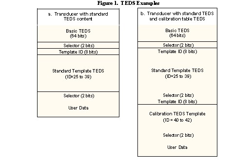
The IEEE 1451.4 specification defines a TEDS as consisting of multiple sections chained together to form a complete TEDS. The first section is the Basic TEDS, comprised of the essential identification information. Typically, one IEEE standard TEDS that defines the important properties for a particular sensor type follows the Basic TEDS. Optionally, this standard template TEDS can be followed by a calibration template. Two-bit selectors in the TEDS data indicate the following section. Finally, the end section of the TEDS is specified as open user area.
TEDS data that is programmed into an EEPROM, as opposed to a virtual TEDS file, also includes a checksum value, which is not included in Figure 1.
Basic TEDS
The first 64 bits of the transducer TEDS is the Basic TEDS. The Basic TEDS uniquely identifies the transducer and includes the Manufacturer ID (14 bits), model number (15 bits), version letter (5-bit character code), version number (6 bits), and serial number of the device (24 bits). This data is organized according to the format described in Table 1 in a non-volatile memory.
Table 1. Basic TEDS Content
Bit Length
| Allowable Range
| |
| Manufacturer ID | 14
| 17 - 16381
|
| Model Number | 15
| 0-32767
|
| Version Letter | 5
| A-Z (data type Chr5)
|
| Version Number | 6
| 0-63
|
| Serial Number | 24
| 0-16777215
|
NOTE — Many transducers are manufactured using draft versions (D0.9x) of this standard, which described a different format for the basic TEDS than that used in this standard. For information about these see Appendix A.
The Manufacturer ID is an enumeration of manufacturers. Several IDs are assigned to early adopters, and future assignments will be managed by IEEE. These ID assignments will also be available in an ASCII text file available from the IEEE or software providers. Software can use this file to display the manurfacturer names. Values 0-16 and 16382-16383 are reserved for special uses, such as node lists in a multi-node configuration, and user-defined templates.
The application and assignment of the remainder of the Basic TEDS are left to the discretion of the manufacturer. Specifically, the Model Number may be defined as a enumeration of the model name for a given manufacturer. This enumeration may be available from manufacturers as an ASCII file for software applications.
Standard Templates - Transducer Types
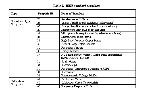
The standard defines a collection of templates for common classes of transducers as listed in Table 2. Templates 25 through 39 are transducer type templates that contain properties that are needed for the specific types of transducers. Templates 40, 41, and 42 are calibration templates and can be used with one of the transducer type templates.
The tables in the following sections summarize the contents of each IEEE standard template. Each row of the table corresponds to a property command (designated in templates with the % sign) or control command that utilizes bits from the TEDS, such as a Select Case. The first column in many of the tables, labeled Select, indicate the different cases for Select Cases in the templates. For example, a 2 bit Select Case read from the TEDS may have four different cases, each containing a section of template that is used for the corresponding Select Case value.
The tables also detail the number of bits used for each property, the access level (user, calibration, or identification), and the data type. The datatypes used in these standard templates are summarized in Table 3.
Table 3. Data Types Used in IEEE Standard Templates
| Data type | Description |
| UNINT | Unsigned integer |
| Chr5 | 5-bit character |
| ASCII | Standard 7-bit ASCII |
| Date | Number of days since January 1, 1998 |
| Single | Single-precision floating point |
| ConRes | Constant resolution. This is a custom data type for compressed floating point values that provides a linear mapping of a defined interval |
| ConRelRes | Constant relative resolution. This is a custom data type for compressed floating point values that provides a logarithmic mapping of a defined interval |
| Enumeration | References a defined enumerated data type defined in the template |
ConRes and ConRelRes provide a method of coding non-integer values with minimal bit usage by defining a limited range over which the bits are mapped. The range and resolution for ConRes and ConRelRes properties are listed in the template.
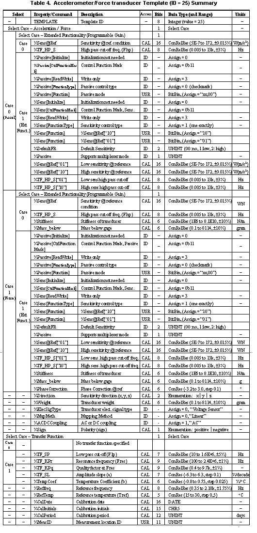
Template 25: Accelerometer and Force Transducers
This template is intended for use with dynamic accelerometers and force transducers which are constant-current pwered, or IEPE.
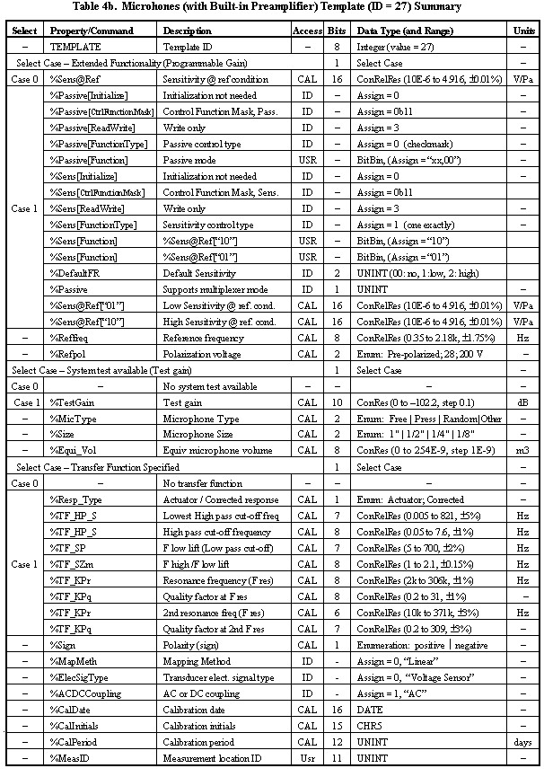
Template 27: Microphones (with Built-in Preamplifiers)
This template is intended for measurement microphones that include an integrated preamplifier. Typically, these devices will have a constant-current powered, or IEPE, interface.
Templates 26, 28, 29 and 43
Templates 26 and 43 are intended for charge amplifiers, with the provision for describing an attached piezoelectric transducer, either an accelerometer or force transducer. Template 28 is a microphone preamplifier template, which can specify an attached microphone capsule. Template 29 is a template describing a capacitive microphone.
Details for the contents and makeup of templates 26, 28, 29, and 43 are included in Annex A of the IEEE 1451.4 specification.
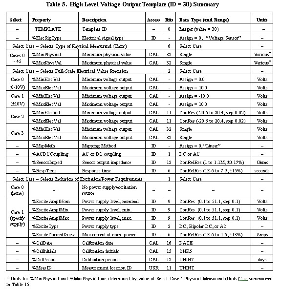
Template 30: High-Level Voltage Output Template
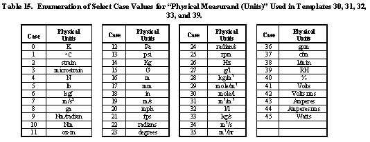
This template is a general-purpose template designed for use with a very wide range of sensors. Virtually any sensor with an analog voltage output can use this template. The first 6-bit Select Case indicates the physical measurand and the corresponding units (such as PSI, N, m/s2, mm, %, etc.).
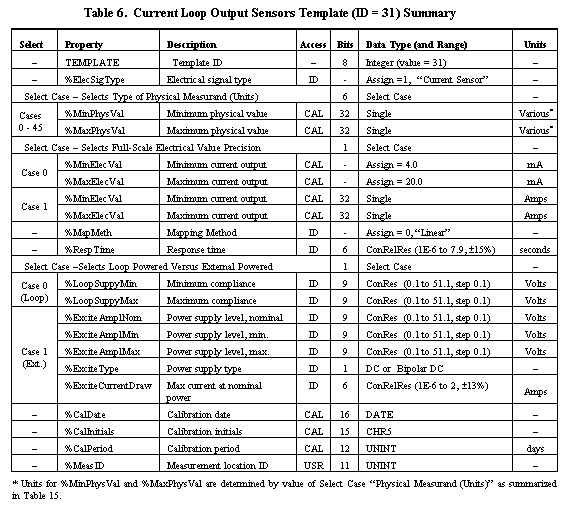
Template 31: Current-Loop Output Template
Like the voltage output template, this template is a general purpose template designed for use with a very wide range of sensors. Virtually any sensor with a current loop output (typically 4-20 mA or 0-20 mA) can use this template. The first 6-bit Select Case indicates the physical measurand and the corresponding units (such as PSI, N, m/s2, mm, %, etc.).
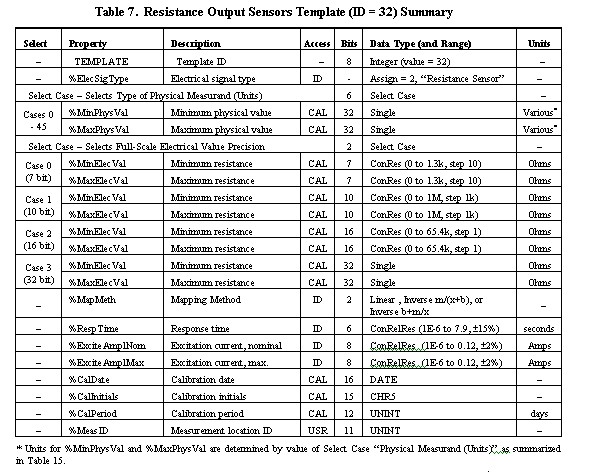
Template 32: Resistive-Output Sensors Template
This template is a general-purpose template intended for any sensor whose electrical output is a variable resistance. If a resistive sensor is configured as a potentiometer, template 39 may be more appropriate. The first 6-bit Select Case indicates the physical measurand and the corresponding units (such as PSI, N, m/s2, mm, %, etc.).
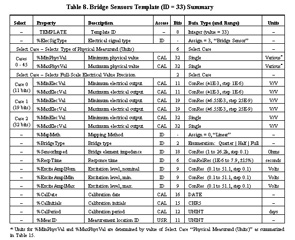
Template 33: Bridge Sensors Template
The bridge sensors template is intended for any sensor whose electrical output interface is a resistive bridge with a linear output. For example, this may be a load cell, pressure sensor, or accelerometer. The first 6-bit Select Case indicates the physical measurand and the corresponding units (such as PSI, N, m/s2, mm, %, etc.).
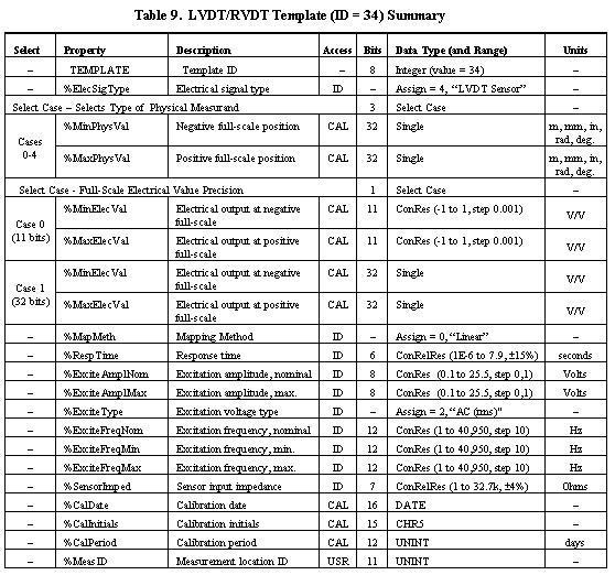
Template 34: AC LVDT/RVDT Template
The bridge sensors template is intended for AC-based linear variable differential transformer (LVDT) and rotary variable differential transform (RVDT) sensors. The first 3-bit Select Case indicates the physical measurand and the corresponding units (such as m, mm, inches, radians, or degrees).
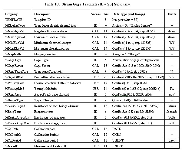
Template 35: Strain-Gage Template
The strain-gage template is intended for strain gauges used in a bridge measurement configuration. While the scaling of readings from the bridge is based on the gage factor, and may or may not be linear, the properties for minimum and maximum physical and electrical ranges are still included to define the operating range of the sensor.
Strain gages are unique in that many of the measurement parameters are determined by how the gages is installed and mounted. Therefore, the template includes more properties that are determined by the measurement configuration and the property to which the gauge is mounted. Examples of this are Poisson's coefficient, Young's modulus, and bridge type .
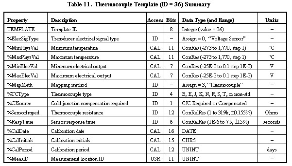
Template 36: Thermocouple Template
The thermocouple template includes designation of the measurement range, electrical output range, and type of thermocouple. Detailed specification of non-standard thermocouple curves is not included in this template.
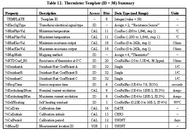
Template 38: Thermistor Template
The thermistor template specifies the operation of a thermistor using the Steinhart-Hart thermistor equation.
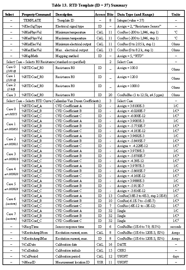
Template 37: Resistance Temperature Detector (RTD) Template
The RTD template, through the RTD Curve select case, allows the specification of a standard DIN curve (cases 0 through 5) or custom curve (cases 6 and 7) using Callendar-Van Dusen coefficients.
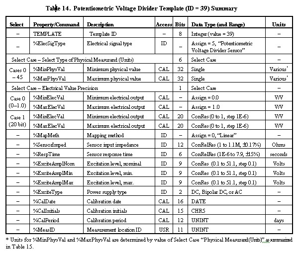
Template 39: Potentiometric-Voltage Divider Template
Tempate 39 is intended for sensors whose outputs are configured as a potentiometer, in a resistive voltage divider configuration. The first 6-bit Select Case indicates the physical measurand and the corresponding units (such as PSI, N, m/s2, mm, %, etc.).
Standard Templates - Calibration Templates
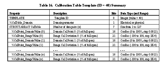
The IEEE standard includes three standard templates designated as calibration templates that you can use in conjunction with one of the standard transducer templates in the previous section. The calibration table and calibration curve templates provide mechanisms for fully specifying the input-versus-output curves for the sensor.
The Calibration Table Template (ID = 40) allows the inclusion of mulitple data pairs to specify the input-output function of the sensor. The Calibration Table Template uses the minimum and maximum physical and electrical values contained in the standard transducer template, and specifies an arbitrary number (value n in Table 16) of data pairs within these ranges.
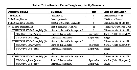
The Calibration Curve Template (ID = 41) allows the specification of the input-output function of the sensor as a multi-segment multi-polynomial curve. The Calibration Curve Template uses the minimum and maximum physical and electrical values contained in the standard transducer template, and specifies an arbitrary number of polynomial curves within these ranges.
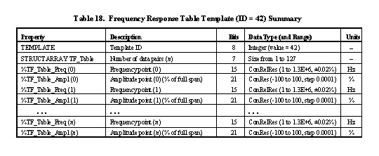
The Frequency Response Table Template (ID = 42) allows the specification of the frequency response function of the sensor as a set of amplitudge-frequency data pairs.
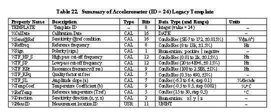
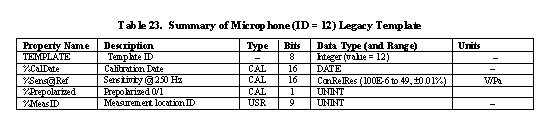
Appendix A - Legacy Transducer Templates (v0.9)
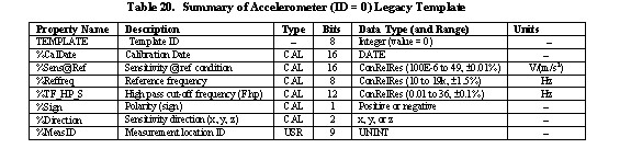
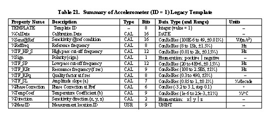
Many transducers are in use with a preliminary version of the IEEE 1451.4 standard designated as v0.9. The TEDS in these sensors use a different format for the Basic TEDS as well as different templates. Although templates with ID values 0 through 24 have been in use, the following tables summarize the most poplular legacy templates, along with the Basic TEDS used in these sensors.
Table 19. Basic TEDS Content for v0.9 Legacy Sensors
Bit Length
| Allowable Range
| |
| Manufacturer ID | 12
| 17 - 4095
|
| Model Number | 16
| 0-65535
|
| Version Letter | 5
| A-Z (data type Chr5)
|
| Version Number | 6
| 0-63
|
| Serial Number | 24
| 0-33554431
|
See Also:
Reading Smart TEDS Sensors and Virtual TEDS Files in LabVIEW