Power Supply Line and Load Regulation and Cascading Considerations
Overview
Learn about specific programmable DC power supply applications, including load considerations, line and load regulation, cascading the outputs of a power supply, and switching power supply signals. This tutorial is part of the Instrument Fundamentals series.
Contents
- Line and Load Regulation
- Load Considerations
- Cascading Power Supply Channels
- Summary of Key Power Supply Line and Load Regulation Considerations
Line and Load Regulation
For a power supply to maintain a stable output, it is important to make sure that it can maintain a given output regardless of changes in the input voltage, connected device, or load. Line regulation refers to a power supply’s ability to maintain its output voltage given changes in input voltage. This is especially important in situations where the power supply’s input source is unstable or if the power supply is not line regulated, which could cause large output swings.
DC power supplies convert an AC input power source to a desired DC output level. Some DC power supplies require additional power from an auxiliary power supply to achieve the desired output levels. Line regulation is commonly published for power supplies that require an auxiliary power supply, but is not specified otherwise. Therefore, you should not be alarmed if a particular power supply does not publish a line regulation specification.
Line regulation involves a power supply’s stability in relation to its input voltage; load regulation is a power supply’s ability to maintain a constant output level given changes in its load. For example, if a 10 W power supply is set to output 10 V in constant voltage mode, then it should remain at 10 V whether it is outputting 1 mA or 1 A of current. Load regulation is the measure of how much you can expect the output to change across the full output capability of the supply. Alternatively, in constant current mode, load regulation refers to the amount of change in output current in relation to the change in voltage drop.
Load Considerations
As mentioned before, different load conditions can have an impact on the ability of a programmable DC power supply to perform as expected. You should exercise caution when sourcing power to capacitive, inductive, and reverse-current loads. Improper use can cause ringing in your output signal or damage your power supply. Ringing in a power supply signal is an undesired oscillation of the output voltage as the power supply attempts to recover from a transient caused by a sudden change in current. Ringing affects a system’s ability to stabilize, which increases measurement time and, if the oscillation peaks are high enough, can even damage connected circuitry. Below, you can find general guidelines for different load conditions; however, when in doubt, reference your power supply documentation for more information.
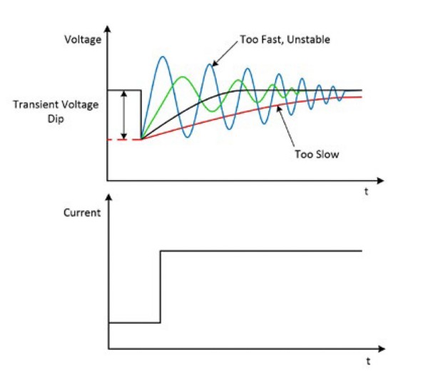
Figure 1. Transient response can affect measurement time and accuracy if unstable or too slow.
Capacitive Loads
Generally, a power supply remains stable when driving a capacitive load, but certain loads can cause ringing in the transient response of the device. The slew rate of a power supply is the maximum rate of change of the output voltage as a function of time, which is directly related to transient response. When using a power supply to drive a capacitor, the slew rate is limited to the output current limit divided by the total load capacitance, as shown below.
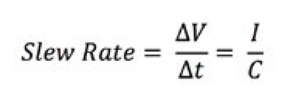
Using the slew rate formula, you can see that the larger the load capacitance, the slower the change in output voltage. If the transient response is too slow, then measurement time could be negatively affected as you must wait for the system to stabilize before taking accurate measurements. However, if the slew rate is too high, then ringing can occur. Furthermore, capacitors are commonly used to dampen ringing in other load conditions.
Inductive Loads
A power supply typically remains stable when driving an inductive load in constant voltage mode. If an inductive load is driven by a power supply operating in constant current mode, specifically in higher current ranges, the power supply can become unstable. In these situations, increasing output capacitance may help improve the stability of the system.
Some power supplies have a user-programmable output capacitance option, which gives you the ability to choose a higher capacitance setting to reduce the chance of ringing. Alternatively, you can provide an external capacitance parallel to your load, which dampens ringing. Typical capacitor values used to reduce ringing when driving an inductive load are 0.1-10 µF. However, as described in the previous section, the larger the capacitance, the slower the output response. Therefore, you should use the minimum capacitance required to reduce the effects of ringing. Typically, you want the output voltage to recover from transients as fast as possible to limit the time that your circuit is receiving undesired voltage levels. The quicker your system returns to a stable output level, the quicker you can take your measurements, which results in a shorter overall test time. Refer to your power supply documentation for more information.
Reverse Current Loads
Occasionally, an active load may pass a reverse current to the power supply. Power supplies not designed for four-quadrant operation may become damaged if reverse currents are applied to their output terminals. Reverse currents can cause your power supply to move into an unregulated mode. To avoid reverse currents, you can use a bleed-off load to preload the output of the device. Ideally, a bleed-off load should draw the same amount of current from the device that an active load may pass to the power supply.
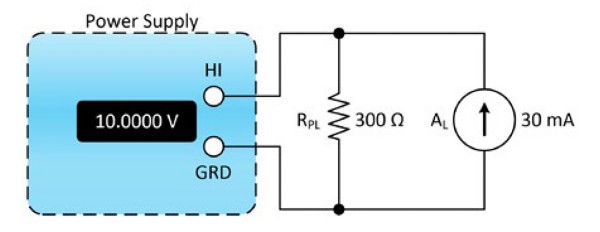
Figure 2. Use a bleed-off load to protect your power supply from the damage that reverse currents can cause.
For example, suppose your power supply is operating in constant voltage mode, supplying 10 V to an active load that can produce a 30 mA reverse current. In this case, a parallel resistor serves as a bleed-off load to preload the power supply output. The value of the bleed-off resistor should be such that the current flowing out of the power supply output is greater than, or equal to, the reverse current produced by your active load. Dividing 10 V by 30 mA suggests using a preload resistance of 333 Ω, effectively matching the reverse current and preventing damage to the power supply.
Choosing Hardware with Overload Protection
As described in the previous sections, it’s important to understand the load conditions of your equipment and testing environment, but you can also choose hardware that will help to protect your investment should something happen. NI PXI Programmable Power Supplies include features such as channel output protection, auxiliary power input protect, and overtemperature protection.
Cascading Power Supply Channels
Output voltage and current can be increased by cascading the outputs of a multichannel power supply or multiple power supplies. Sometimes an application requires more voltage or current than a single channel of a power supply can output. Cascading power supply channels can extend an output’s voltage and current capabilities, but you should practice extreme caution when doing so, as this can easily damage the power supply or user if not done correctly.
Cascading Power Supply Channels to Increase Voltage Output
If your power supply offers isolated outputs, or if you have multiple isolated power supplies available, then you can easily extend the maximum voltage output range by cascading channels in series. To cascade multiple isolated channels from a single power supply or multiple power supplies, connect the channels in series as shown in Figure 3. The resulting voltage supplied to your load will be equal to the sum of individual channel voltages.
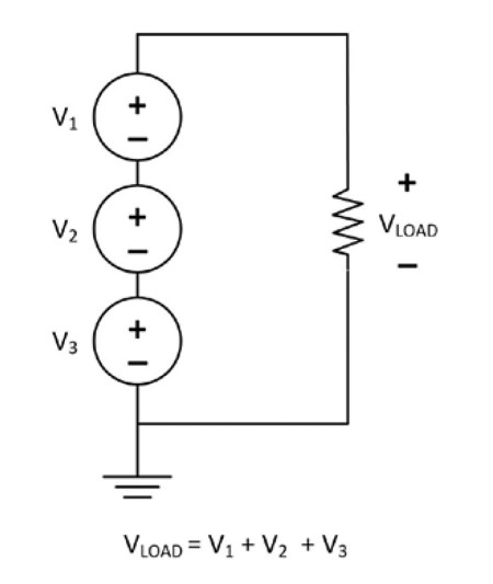
Figure 3. Increase output voltage by cascading isolated power supply channels.
Important: When cascading power supply channels, make sure that the voltage between every pin and device ground is less than the maximum specified isolation voltage. For example, if your device’s isolation specification states that each channel is isolated up to 60 VDC from ground, then the voltage between each pin and ground should be less than 60 VDC. Failing to adhere to this specification can damage the device and/or harm the user.
NI PXI Programmable Power Supplies offer channels with isolated outputs, so you can cascade multiple channels in series to generate greater output voltage. Refer to the documentation and specifications document for detailed information about and recommendations for how to combine output channels.
Cascading Power Supply Channels to Increase Current Output
If your power supply offers isolated outputs, or if you have multiple isolated power supplies available, then you can easily extend the maximum current output range by connecting channels in parallel. To increase current output by cascading multiple isolated channels from a single power supply or multiple power supplies, connect the channels in parallel as shown in Figure 4. The resulting current supplied by the power supply to your load will be equal to the sum of individual channel currents.
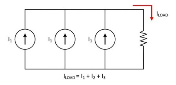
Figure 4. Increase output current by cascading isolated power supply channels.
Summary of Key Power Supply Line and Load Regulation Considerations
- Line regulation is the ability of a power supply to maintain the output voltage given changes in the input line voltage.
- Load regulation is the ability of a power supply output to remain constant given changes in the load.
- You should exercise caution when sourcing power to capacitive, inductive, and reverse-current loads. Improper use can cause ringing in your output signal or damage your power supply.
- Ringing in a power supply signal is an undesired oscillation of the output voltage as the power supply attempts to recover from a transient caused by a sudden change in current, which can increase test time or even damage connected circuitry with high-voltage spikes.
- The slew rate of a power supply is the maximum rate of change of the output voltage as a function of time.
- If an inductive load is driven by a power supply operating in constant current mode, increasing output capacitance may help improve the stability of the system.
- Reverse currents can cause your power supply to move into an unregulated mode and may cause damage. Avoid reverse currents by using a bleed-off load to preload the output of the device.
- Output voltage and current can be increased by cascading the outputs of a multichannel power supply or multiple power supplies.
- When cascading power channels, make sure that the voltage between every pin and device ground is less than the maximum specified isolation voltage.
- Carry current describes the amount of current that can pass through a previously closed relay without causing damage. On the other hand, switching current is the maximum rated current that can flow throw the switch as it makes or breaks contact without causing damage.