From 11:00 PM CST Friday, Apr 11th - 1:30 PM CST Saturday, Apr 12th, ni.com will undergo system upgrades that may result in temporary service interruption.
We appreciate your patience as we improve our online experience.
From 11:00 PM CST Friday, Apr 11th - 1:30 PM CST Saturday, Apr 12th, ni.com will undergo system upgrades that may result in temporary service interruption.
We appreciate your patience as we improve our online experience.
Many applications require precise control of timing and the ability to synchronize multiple operations. NI M Series data acquisition devices provide excellent tools for synchronization and are well suited for these applications. This paper will present and analyze the recommended methods for multifunction and multidevice M Series synchronization with NI-DAQmx measurement services and LabVIEW, which is the graphical development environment for creating flexible and scalable test, measurement, and control applications rapidly and at minimal cost. With LabVIEW, engineers and scientists interface with real-world signals, analyze data for meaningful information, and share results and applications. Additionally, this paper will present the recommended method to synchronize E Series and M Series devices.
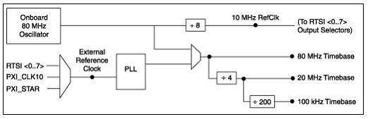
Before discussing synchronization, it is helpful to first understand the different clocks present in M Series devices. The NI-STC 2 timing and controller ASIC on M Series devices generates several timebases by dividing down an 80 MHz timebase. This 80 MHz timebase is derived in one of two ways – either from the 80 MHz onboard oscillator or from the phase-lock-loop (PLL) circuit , as shown in Figure 1 below. When the reference clock for the PLL is shared among devices, the 80 MHz timebase produced from the PLL will be synchronized among those devices. Thus, all the clocks derived from that 80 MHz timebase or the resulting 20 MHz timebase will also be synchronized. Due to the way signals are divided, the 100 kHz timebase will not be in phase with the input to the PLL. These timebase signals are used internally as clock sources for the analog input, analog output, and counter/timers subsystems of the device. For example, the analog input subsystem will divide down one of these timebases to create its AI Sample Clock. From this 80 MHz onboard oscillator, each M Series device also generates its own 10 MHz reference clock, which can be used for synchronization in a multidevice system.
Figure 1 Clock Routing Circuitry of an M Series Device
Sample clocks for analog operations on M Series devices are typically obtained by dividing down either the 20 MHz or 100 kHz internal timebase. The counter/timers are the only subsystem that can directly use the 80 MHz timebase. It is also possible to source other external and internal signals such as the PXI_STAR trigger, analog comparison event, or signals from PFI lines or the RTSI bus. For more information about AI and AO sample clock derivation, read the timing signal sections of the M Series User Manual .
Setting up the hardware to allow synchronization is accomplished through the Measurement & Automation Explorer (MAX), which is a program that provides access to your NI devices so you can configure your hardware and software accordingly. The steps necessary for configuring your hardware are different depending on whether the device is a PCI board or a PXI module. For PCI boards, a RTSI cable, that should by physically connected to all of the boards between which you want to route signals, must be virtually created and registered in MAX. Once the RTSI cable is created, the boards will need to be added to the RTSI cable, and the NI-DAQmx driver can route signals between devices accordingly. This feature is discussed in more detail in the Timing and Synchronization Features of NI-DAQmx tutorial. For PXI modules, the idea is the same, but the only thing that needs to be done is to identify the PXI chassis. There are no cables required for PXI modules because the equivalent of the RTSI bus is contained in the backplane of the PXI chassis. This too is discussed in the above mentioned tutorial.
Synchronization can be broken down into two major types: multifunction and multidevice. Multifunction synchronization includes operations that occur simultaneously on a single device. In other words, operations such as simultaneous analog input/analog output and simultaneous digital input/analog output fall under the heading multifunction synchronization. For the purposes of this paper, multifunction synchronization is divided into two categories: sharing a start trigger and sharing a sample clock. Multidevice synchronization refers to synchronizing operations across multiple devices in your system and is discussed later in the examples listed below.