What Is NI Switch Executive?
Overview
NI Switch Executive is an intelligent switch management and routing application. It offers the latest revolution in switching software for automated test equipment (ATE) systems. With NI Switch Executive, you gain increased development productivity by interactively configuring and naming switch modules, external connections, and signal routes. You can also increase test code reuse and system performance using switch programming with NI TestStand, LabVIEW, LabWindows™/CVI, and Measurement Studio. Ultimately, NI Switch Executive accelerates development time and simplifies switch system maintenance, thus lowering your cost to test.
Contents
- Accelerated Switch System Development
- Simulation
- Excel Integration
- Integration with LabVIEW and NI TestStand
- Simple System Maintenance
- Conclusion
Accelerated Switch System Development
NI Switch Executive accelerates switch system development with its intuitive configuration environment in which you can create NI Switch Executive “virtual devices.” If you are familiar with performing data acquisition measurements using Measurement & Automation Explorer (MAX), creating virtual devices is similar to creating virtual channels. You use the NI Switch Executive virtual device configurations to combine a variety of IVI-compliant NI and third-party switches to create a single virtual switch device. Once you have defined the switching hardware as a virtual switch device, you can specify additional properties of the switching system. These properties for each switch device include:
- Desired channels
- Hardwires
- Routes
- Route groups
- Physical attributes
The physical attributes include:
- Wire mode
- Bandwidth
- Impedance
- Settling time
- Maximum voltage
- Carrying current
- Carrying power
Using NI Switch Executive, you can store the physical attributes associated with each switch configuration and intelligently use the information to help you determine proper switch routes. This helps you protect the large investment in switch hardware from being overdriven or routing a high-frequency signal across a low-frequency switch device.
The NI Switch Executive accelerated application configuration environment also includes tools for configuring the channels used in complex switching systems. With this, you can create alias names and add unique comments for each channel, greatly simplifying the maintenance of hundreds or thousands of switch channels in large switch systems because you can refer to a channel as “DMM” or “Scope” instead of “c0” or “c2.” You can also take advantage of the channel alias feature when using multiple switch devices. Traditionally switch systems with multiple switches had multiple channels of the same name, such as “c0” or “c2,” on each switch device representing completely different inputs or outputs. With NI Switch Executive, you can assign different names to these channels. In the channel mode, you can also configure each channel in your switch system as normal, configuration, or source to ensure proper validation of the final switch configuration. Normal mode indicates a typical channel in a switch system; configuration mode specifies that the channel is used as a path to connect two normal channels; and the source mode is allocated for channels providing an input voltage or current. Figure 1 demonstrates how you can quickly configure your channels using the in-place channel alias editing feature included in the Graphical Configuration Utility.

Figure 1. NI Switch Executive Graphical Configuration Utility
Once you have configured all of the required channels, NI Switch Executive provides two innovative utilities to assist you in connecting pairs of channels to form routes.
First is the Graphical Configuration Utility for NI Switches. Shown in Figure 1, this point-and-click utility provides an illustrated representation of your NI switch module that you can configure with a few clicks of your mouse. If you want to create a route in your switch matrix, click on the “Create route” button, find the intersection of the row and column that you would like to connect, and click. You can create route groups in the same way. Click on the “Create route group” button and click on all of the intersections that you want to include in your route group (Figure 2). To configure channel aliases, locate the row or column of interest, click, and rename.
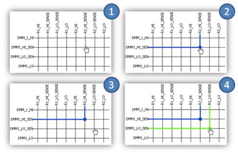
Figure 2. Creating a Route Group Using the Graphical Configuration Utility
Second is the text-based route configuration tool. In this environment, you select two channels to connect from the list of alias channel names or full channel names. Based on your selection the built-in intelligence of NI Switch Executive recommends an available route. The suggested route is displayed, including any hardwires that you must cross between multiple switch devices in the system. You can either accept the suggested route or manually specify the route. After you have selected the route, you can name it using an alias name for quick reference in test software programs. Additionally, each test you perform on a UUT often requires disconnecting and connecting multiple routes before testing. To assist in this process, you can use NI Switch Executive to group multiple routes together to form a route group. You can name and access this route group by an alias name. When programming the UUT tests, you can refer to the route group alias name in the test program, and all of the routes specified in that route group are connected or disconnected.
Simulation
For each NI Switch Executive virtual device configuration in MAX, NI Switch Executive provides the option to validate the entire switch configuration in simulation mode. By running through your configuration in simulation mode, you ensure that there are no gross errors that could damage the switching hardware or UUT. You receive a report of any problems associated with the configured routes or route groups for easy troubleshooting and prompt corrective action. You can also generate an HTML-based report of the entire switch configuration with the click of a button for quick documentation and external reference to the entire configuration of your switch system. You can also quickly save each NI Switch Executive virtual switch device configuration to an eXtended Markup Language (XML) file, which you can load on deployed test systems for instant configuration and repeatability.
Excel Integration
With the Excel Import/Export feature, you can transport your entire switch configuration into the familiar Microsoft Excel environment (Figure 3). Once there, you can use text editing features of Microsoft Excel such as find/replace and click-and-drag formulas to multiply your channel aliases, routes, and routing groups. Scaling your configuration in Excel also promotes a naming convention that makes your system easy to integrate with the NI TestStand test management software.
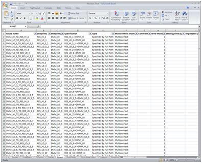
Figure 3. Microsoft Excel Switch Configuration
Integration with LabVIEW and NI TestStand
NI Switch Executive integrates perfectly in the complete NI integrated test architecture for a much improved development experience when building ATE test systems. With NI Switch Executive software, you can extract the switching functionality you need at different levels within the integrated test executive software.
Figure 4. NI Switch Executive Integration in NI TestStand
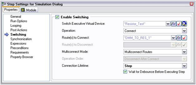
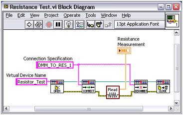
Figure 5. NI Switch Executive Integration in LabVIEW
For instance, you can easily integrate NI Switch Executive within the NI TestStand test management environment for controlling your switch hardware on a per-test basis (Figure 4). You can also use NI Switch Executive to program switches within individual test modules written in the popular test languages, such as LabVIEW (Figure 5), LabWindows/CVI, and NI Measurement Studio for Visual Studio.
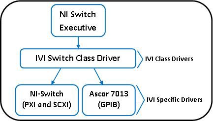
Figure 6. NI Switch Executive Use of Interchangeable Virtual Instrument (IVI) Standard
Simple System Maintenance
Lastly, automated switch systems are easier to maintain through the use of NI Switch Executive. With the interactive and easy-to-use configuration environment, you can quickly change your switch routes and hardware to reflect changes in the product. Because NI Switch Executive takes advantage of the Interchangeable Virtual Instruments (IVI) standard as shown in Figure 6, you can quickly interchange your IVI-compliant switch hardware with another version of the switch or a switch from a different vendor without having to rewrite any of your test code (assuming you are using IVI Switch Class Driver functions). To learn more about IVI, visit ni.com/ivi.
Conclusion
As UUT complexity continues to grow with each new product that emerges, the number of test points that you must connect increases substantially. The rise in test points also means a significant increase in switch complexity. NI Switch Executive alleviates many of the challenges in developing and maintaining your switching system ultimately lowering the cost of your test system.
Related Links
Products and Services: NI Switch Executive
Guides to Getting Started: Test Systems