Design Templates for CompactRIO Custom I/O Module PCB Design
Overview
Correct component placement is one of the most critical aspects of the successful design of any Printed Circuit Board (PCB). This is especially true in the design of a custom I/O module for CompactRIO. The PCB must adhere to very specific size restrictions, and the 15-pin D-Sub Connector must also be placed correctly in order to provide a clean interface between the module and the backplane. Furthermore, if external I/O signals are to be used, the connectors must be placed appropriately in order to be able to utilize National Instrument's prefabricated module housings.
Contents
- Basic C Series Module Printed Circuit Board Design
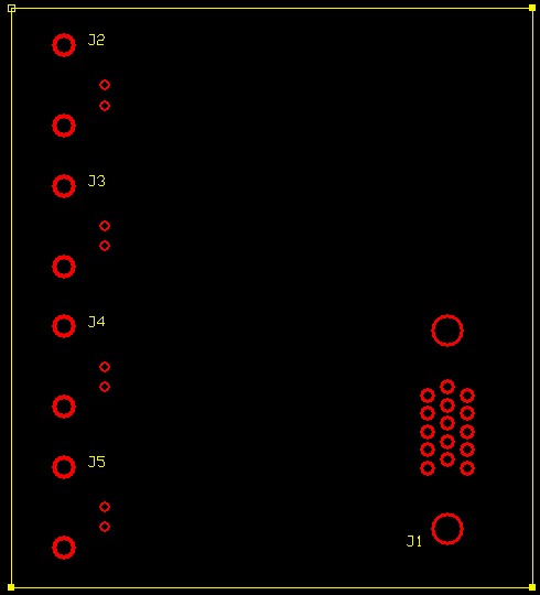
- 4 BNC Inputs C Series Module Printed Circuit Board Design
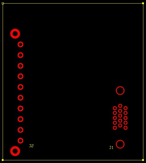
- 10 Input Screw Terminal Connector C Series Module Printed Circuit Board Design
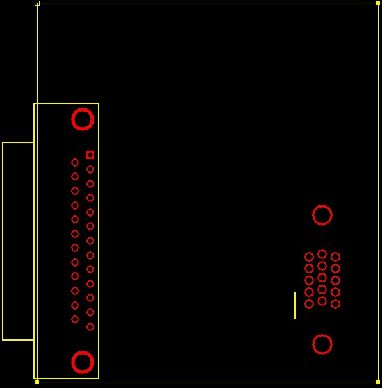
- 25 Pin DSub Connector C Series Module Printed Circuit Board Design
- Additional Resources
CompactRIO module templates are included in the Board Outline database in the NI Ultiboard PCB layout tools to save time during the board layout phase. The following document provides a set of printed circuit board templates that can be used with many layout software products.
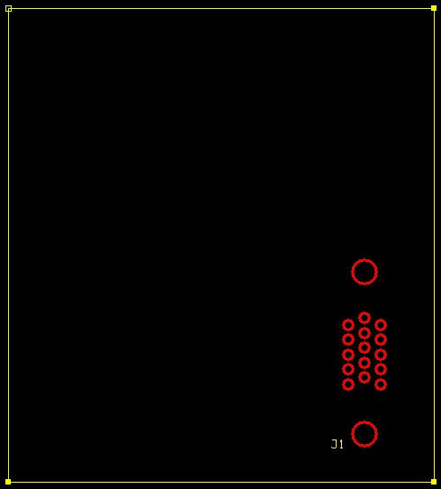
In each of the designs, the recommended board dimensions are used, and the correct footprint for the 15-pin D-Sub connector is properly placed.
Basic C Series Module Printed Circuit Board Design
4 BNC Inputs C Series Module Printed Circuit Board Design
10 Input Screw Terminal Connector C Series Module Printed Circuit Board Design
25 Pin DSub Connector C Series Module Printed Circuit Board Design
Additional Resources
- Information on custom module development for CompactRIO
- Learn more about Multisim and Ultiboard. See Multisim and Ultiboard application notes and tutorials.
- CompactRIO Third-Party Products, Reference Designs and NI Single-Board RIO Resources
