Transition from Traditional NI-DAQ (Legacy) to NI-DAQmx in LabVIEW
Overview
This reference guide demonstrates how to migrate applications written in Traditional NI-DAQ (Legacy) to NI-DAQ™mx. The purpose of this document is to show the key differences between the two data acquisition (DAQ) drivers, as well as discuss some common tips to use while programming in NI-DAQmx.
Contents
- Overview
- Analog Input
- Analog Output
- Digital Output
- Counter Pulse Train Generation
- Shared Clocks over RTSI (Interoperability of Traditional NI-DAQ (Legacy) and NI-DAQmx)
- Tips and Tricks for NI-DAQmx in LabVIEW
- Additional Resources
Overview
NI recommends starting with a new VI and using the old VIs written in Traditional NI-DAQ (Legacy) as a guide. Although many of the programming techniques are similar, there are some slight differences that will be pointed out in this document. Please note that this article is intended to be a supplement to the other help documents available, not a substitution. After you understand what is described in this article, you should have a clear idea of the main differences to keep in mind when programming in NI-DAQmx.
Since it is recommended to start code from scratch, here are a few guidelines and suggestions to make that transition as easy as possible. A helpful tool available since LabVIEW 7.0 and later is the DAQ Assistant. With this assistant, you can designate what you want your code to do in Measurement & Automation Explorer (MAX), and then generate code based on that task. After generating the code, you can then edit it by adding property nodes or changing the configuration to meet the needs of your specific application. If you would like more information on how the DAQ Assistant works, refer to Taking an NI-DAQmx Measurement in LabVIEW.
One major difference between the two drivers is in the palettes. In Traditional NI-DAQ (Legacy), there is a different palette for each type of operation, such as a digital palette for digital operations, an analog input palette for all analog input operations, and so on. In NI-DAQmx, just one set of VIs is used for all operations, and you can configure each VI for a specific type of acquisition. For example, in Traditional NI-DAQ (Legacy), you use the AI Config.vi to configure a channel or set of channels for analog input. In NI-DAQmx, you use the DAQmx Create Channel.vi, and configure this VI for Analog Input: Voltage. This distinction makes it easier to become familiar with the specific VIs needed to perform various operations.
Analog Input
(Click to Enlarge)
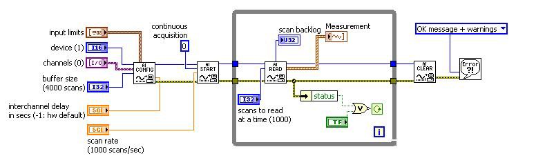
Figure 1. Traditional NI-DAQ (Legacy): Cont Acq&Graph (buffered).vi
(Click to Enlarge)
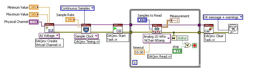
Figure 2. NI-DAQmx: Cont. Acq&Graph Voltage-Int Clk.vi
This example shows the difference between Traditional NI-DAQ (Legacy) and NI-DAQmx when performing continuous analog input with an internal clock. To translate a program written with Traditional NI-DAQ (Legacy) into NI-DAQmx, follow these steps:
- First, replace the
AI Config.viwith theDAQmx Create Channel.vi. - Configure the
DAQmx Create Channel.vifor Voltage by selecting from the dropdown below the VI Analog Input>>Voltage. This information needs to be set because theDAQmx Create Channel.viis a polymorphic VI used for all types of acquisition. This is unlike Traditional NI-DAQ (Legacy) where different VIs are used for the different types of acquisitions. - Create the controls on the front panel so that the data types correlate. Notice that there are no longer device number and channel name controls because they are combined into one control denoted by the Physical Channel. Another configurable input on this VI is the Input Terminal Configuration. The board automatically defaults to Differential mode. The referencing mode is no longer set in MAX, to measure in NRSE or RSE, you must specify it here.
- Now insert the
DAQmx Timing.viafter theDAQmx Create Channel.vi. TheDAQmx Timing.visets the sample rate and creates the buffer for continuous acquisition. Since continuous acquisition is specified, LabVIEW automatically creates a buffer to make use of buffered acquisition. - Replace the
AI Start.viwith theDAQmx Start Task.vi, which is similar in functionality. The most significant difference between the two is that the sample rate is no longer set when you start the acquisition, but instead set with theDAQmx Timing.vi. - Replace the
AI Read.viwith theDAQmx Read.vi. - Configure the
DAQmx Read.vifor Analog»Multiple Channels»Multiple Samples»1D Waveform. - Create the constants, controls, and indicators so they are connected to the correct terminals.
- Replace the
AI Clear.viwith theDAQmx Clear Task.vi. The inputs to this VI are the same and it performs the same function.
Analog Output
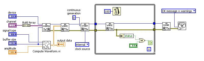
This example shows the difference between Continuous Analog Output in Traditional NI-DAQ (Legacy) and NI-DAQmx. To convert a program written in Traditional NI-DAQ (Legacy) to NI-DAQmx, follow these steps:
- First, replace the
AO Config.viwith theDAQmx Create Channel.vi. - Create all the controls so that the data types match. In NI-DAQmx, the Physical Channel input specifies the device number as well as the channel number, instead of the two separate controls required in Traditional NI-DAQ (Legacy).
- Replace the
Compute Waveform.viwith a very similar VI calledWaveform Buffer Generation.vi. This new VI passes the task through the waveform generation VI, as opposed to having to wire around it as in Traditional NI-DAQ (Legacy). - Replace the
AO Write.viwith both theDAQmx Timing.viand theDAQmx Write.vi. - Configure the
DAQmx Timing.vifor the Sample Clock. TheDAQmx Timing.vi, when configured for the Sample Clock, specifies the sample mode as well as the clock source to use. - Set the
DAQmx Write.vito use Analog»Single Channel»Multiple Sample»Waveform. - Create the necessary inputs and make sure the data types are equivalent.
- Replace the
AO Start.viwith theDAQmx Start Task.vi. Both of these VIs have similar inputs and outputs and generally perform the same functions. - Inside the while loop, substitute the
AO Write.viwith theDAQmx Is Task Done.vi. Because this example uses continuous generation, you do not necessarily need to use theDAQmx Is Task Done.vibecause the task will not be complete until you press the stop button on the front panel. However, if you are performing a finite generation, this VI is essential to signify the end of the operation. - Replace the
AO Clear.viwith theDAQmx Clear Task.vi. Both of these VIs achieve the same function.
Digital Output
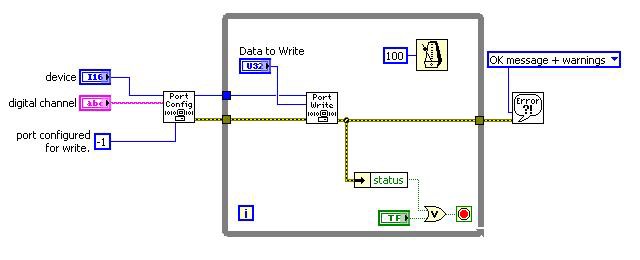
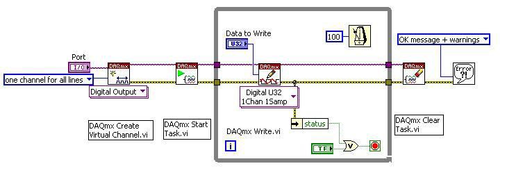
The example above illustrates the difference between doing Digital Port Writes in Traditional NI-DAQ (Legacy) and in NI-DAQmx. To move a Traditional NI-DAQ (Legacy) program to NI-DAQmx, follow these steps:
- First, replace the
DIO Port Config.viwith both theDAQmx Create Channel.viand theDAQmx Start Task.vi. - Configure the
DAQmx Create Channel.vifor Digital Output. - Create controls and make sure the data types of the controls match up correctly.
- When creating the port control, specify the entire port and not just a specific line number.
- Now substitute everything inside the while loop except the Wait function and the stop button with the
DAQmx Write.vi. - Configure the
DAQmx Write.vifor Digital»Single Channel»Single Sample»U8 (Port Format). This VI takes care of writing all the data. - Add a
DAQmx Clear Task.vioutside the while loop to clear the task created for the program.
Counter Pulse Train Generation
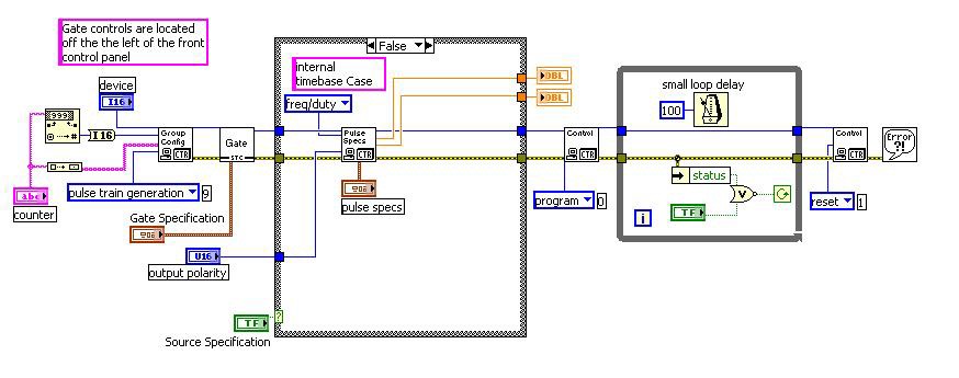
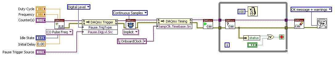
This example demonstrates the difference between doing Continuous Pulse Train Generation in Traditional NI-DAQ (Legacy) and NI-DAQmx. Follow these steps to transition a program written in Traditional NI-DAQ (Legacy) to NI-DAQmx.
- First, replace the
Counter Group Config.viwith theDAQmx Create Channel.vi. - Configure the
DAQmx Create Channel.vifor Counter Output»Pulse Generation»Frequency. - Create separate controls for the Duty Cycle, Frequency, Counter, and Idle State. The Counter control specifies which device as well as which counter to use. The Idle State input informs the counter in which state to start and to which state to return after the pulse train has completed. The
Set Pulse Specs.viis no longer needed because those values are set on theDAQmx Create Channel.viinstead. - Replace the
Counter Gate (STC).viwith a DAQmx Trigger property node. Set the Trigger Type to Digital Level in the property node, and then create a control on the front panel to select the source of the gate. - Insert the
DAQmx Timing.viafter the DAQmx Trigger property node. TheDAQmx Timing.viis configured to Implicit (Counter). This VI indicates the duration of the pulse generation. - Add a DAQmx Timing property node after the
DAQmx Timing.vi. In this case, the timing property node specifies the onboard clock and configures an external clock, if desired. This is used in lieu of the case structure in the Traditional NI-DAQ (Legacy) example. - Replace the
Counter Control.viwith aDAQmx Is Task Done.viinside the while loop. The purpose of this VI is to check when finite generation is finished. For this example, theDAQmx Is Task Done.vican be omitted since it is continuous, but if performing finite generation, you need to include this VI. - Replace the
Counter Control.viwith theDAQmx Clear Task.vi. The inputs to this new VI are very similar, except that the task automatically resets without specifying to do so.
Shared Clocks over RTSI (Interoperability of Traditional NI-DAQ (Legacy) and NI-DAQmx)
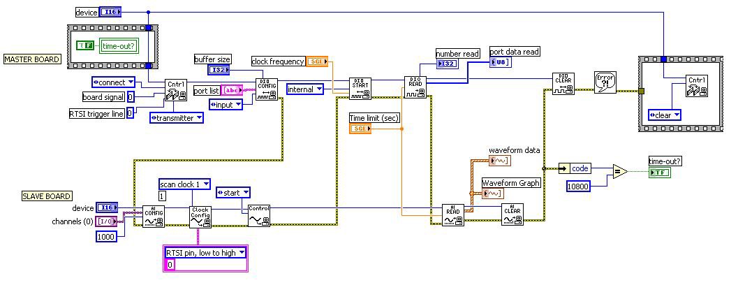
(Click to Enlarge)
Figure 9. Traditional NI-DAQ (Legacy): Share 653x REQ Clock with E Series AI Sample Clock.vi
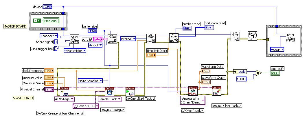
This example illustrates how to synchronize a 653X board with an E Series board. The REQ clock of the 653X is used as the sample clock for an analog input acquisition on the E Series board. This is shown above using Traditional NI-DAQ (Legacy) as well as NI-DAQmx. The example demonstrates the flexibility and the interoperability of the two drivers, and how much clearer RTSI use is in NI-DAQmx. The digital board portion on both examples uses the Traditional NI-DAQ (Legacy) driver, so this explanation describes only how to convert the segment of code running on the E Series board.
- First, replace the
AI Config.viwith theDAQmx Create Channel.vi. - Configure the
DAQmx Create Channel.vifor Voltage by selecting from the dropdown below the VI Analog Input»Voltage. - Create the controls on the front panel and the necessary constants.
- Replace the
AI Clock Config.viwith theDAQmx Timing.vi. TheDAQmx Timing.visets the sample rate and creates the buffer, because continuous acquisition is desired. The buffer is acquired automatically since it is set up for continuous acquisition. One important input to this VI is the Source. Leave the input blank if you want to use the default onboard clock. For this example, however, create a constant and set it to use the RTSI pin that is routed from the digital board (which in this case is /Dev4/RTSI0). Notice that this name permits you to specify a different device number. This is important because NI-DAQmx accomplishes all the internal routing for you. - Replace the
AI Control.viwith theDAQmx Start Task.vi, which is similar in functionality. - Replace the
AI Read.viwith theDAQmx Read.vi. - Configured the
DAQmx Read.vifor Analog»Single Channel»Multiple Samples»1D Waveform. You must provide this information because theDAQmx Read.viis a polymorphic VI used for all types of data acquisition (as opposed to Traditional NI-DAQ (Legacy), where there are many unique VIs for different types of acquisition). - Replace the
AI Clear.viwith theDAQmx Clear Task.vi. The inputs to this VI are the same and they perform the same functionality.
Tips and Tricks for NI-DAQmx in LabVIEW
- Basic DAQ programming (analog input/output, digital input/output) is simpler and more streamlined in NI-DAQmx. There is one basic structure for all DAQ programs that uses the same collection of VIs, instead of having a separate set of VIs for each type of input/output as in Traditional NI-DAQ (Legacy).
- The more advanced concepts such as counters, triggering, timing and synchronization require a shift in programming mindset from Traditional NI-DAQ (Legacy). In NI-DAQmx, you must use property nodes for certain advanced functionality. The property names are descriptive, such as the Clock Source property, which specifies the terminal of the signal to use as the sample clock). For more help, see Getting Started with DAQmx: Basic of DAQmx Property Nodes.
- Start by looking at examples already written in NI-DAQmx.
- Don’t try to convert the Traditional NI-DAQ (Legacy) code you already have. Instead, start from scratch, using the DAQ Assistant to configure your own measurement tasks and generate code for them. Code generation is helpful to see how to set up basic functions. The only issue may be that the configuration code is in a subVI, so you must copy and paste it to the main VI if you want the controls on the front panel of the main VI. Then you can add more functionality and other VIs to the generated code.
- With NI-DAQmx, many of the terminal and signal names have been changed so they are easier to understand and more consistent across NI hardware and software products. This change in terminology is explained in Sampling Terminology for NI-DAQmx and Tranditional NI-DAQ (Legacy).
- At the most basic level, programming in NI-DAQmx involves creating a task, and then reading or writing. A task is just a virtual channel with added features, including custom configuration such as timing, triggering, and scales. Virtual channels are integral to NI-DAQmx, not just an added feature as in Traditional NI-DAQ (Legacy). For more information on tasks and virtual channels please see the NI-DAQmx help, which is installed with NI-DAQmx.
Additional Resources
- Getting Started with DAQmx: Basic of DAQmx Property Nodes
- Sampling Terminology for NI-DAQmx and Traditional NI-DAQ (Legacy)
- Product Documentation: Traditional NI-DAQ User Manual (Archived)
- Product Documentation: NI-DAQmx Installed Documentation
- Transitioning from Traditional NI-DAQ (Legacy) to NI-DAQmx Using ANSI C and NI LabWindows™/CVI