NI CompactRIO Controller: Performance and Throughput Benchmarks
Overview
The CompactRIO controller, based on the LabVIEW RIO Architecture, features the latest technologies such as the powerful 64-bit Intel Atom E3800 System-on-Chip (SoC) Family and Xilinx Kintex 7 FPGAs. The Intel Atom SoC delivers a massive amount of performance and functionality, including an integrated GPU and a multicore processor. The Kintex-7 325T FPGA has almost 3X as many complex logic blocks and over 13X as many DSP slices than the FPGAs in other CompactRIO controllers. The FPGA and processor communicate using the PCI Express bus, which dramatically improves throughput and gives access to 16 DMA channels.
The LabVIEW RIO Architecture, on the new CompactRIO controller, provides the software flexibility to consolidate the HMI and control tasks on the same target and on one operating system. This is possible because of the features of the multicore Intel Atom SoC and NI Linux Real-Time OS. This OS exposes task prioritization to the developer to assign a higher priority to the control tasks over the HMI software tasks running in the same application.
The combination of these technologies dramatically improves system throughput and reduces latency for closed loop control applications. The CompactRIO controller equips embedded designers with flexible, powerful hardware while reducing system complexity and cost.
To demonstrate the capabilities of the CompactRIO controller, the R&D group in National Instruments compiled a series of control and monitoring application benchmark tests. These tests are equally applicable to all dual-core and quad-core variants of the CompactRIO controller (NI cRIO-903x.)
Contents
- Benchmark Setup and Measurement
- Test 1 - LabVIEW FPGA Control Sample Project Performance Benchmark
- Test 2 - Monitoring Application Throughput Benchmark
- Test 3 - Complex Real-World Application Performance Benchmark
- Effect of Embedded UI
- Conclusions
- Next Steps
Benchmark Setup and Measurement
Benchmark tests were designed to represent common control and monitoring applications as well as major tasks found in these applications. The table bellow shows an overview of tests conducted in this study.
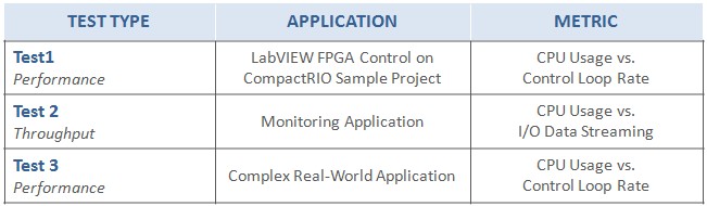
Table 1: Tests implemented on NI CompactRIO controllers to measure application performance and throughput
This study was conducted considering the following hardware targets:
- NI cRIO-9025 | 800 MHz, PowerPC
- NI cRIO-9068 | 667 MHz, ARM Cortex-A9 dual-core
- NI cRIO-903x | 1.33 GHz, Intel Atom dual-core
- NI cRIO-903x | 1.91 GHz, Intel Atom quad-core
- NI cRIO-9082 | 1.33 GHz, Intel Core i7 dual-core
While this study focuses on the CompactRIO controller and how it compares against existing controllers in the same family like the cRIO-9025 in the case of the dual-core variant and the cRIO-9082 in the case of the quad-core variant, representative hardware targets from other CompactRIO families such as the cRIO-9068 are also included as a reference point to show a more complete picture of the range of possibilities that CompactRIO systems offer.
The CPU usage is used as a common metric to compare the relative performance of these CompactRIO controllers. For each of these tests the CPU usage is measured at a steady state whilst varying the number of channels streaming data or control loop rates. These metrics give an idea of the available resources for additional code, higher loop rates, or more streaming channels.
Additional Considerations:
- For CompactRIO systems featuring multicore processors, the results of each individual core are averaged.
- For the CompactRIO controller, the tests were performed with the Embedded UI option both enabled and disabled to measure the impact of this feature on the overall performance of the system.
Test 1 - LabVIEW FPGA Control Sample Project Performance Benchmark
The combination of technologies in the new performance CompactRIO system results in unparalleled performance improvements for complex, real-world applications. To test a control scenario, the LabVIEW FPGA Control on CompactRIO Sample Project was selected. The sample project was extended with an eight channel cubic spline trajectory generation algorithm on the Real-Time controller to further stress the CPU.
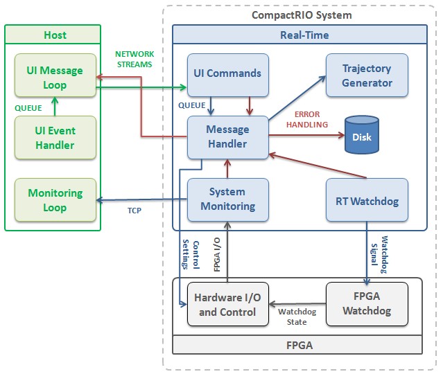
Figure 1: Architectural diagram of the LabVIEW FPGA Control on CompactRIO Sample Project featuring an eight parallel channel cubic spline trajectory generation algorithm
The figure below shows the CPU usage when running the control loop at 1.5 kHz. At this rate, the dual-core performance controlled used roughly 15% of its processor resources. This is a significant improvement over the cRIO-9025 controller, which required 70% of it’s processor resources. Similarly, the quad-core performance controller used 5% of its processor resources, which is very similar to the observed performance of the cRIO-9082 controller.
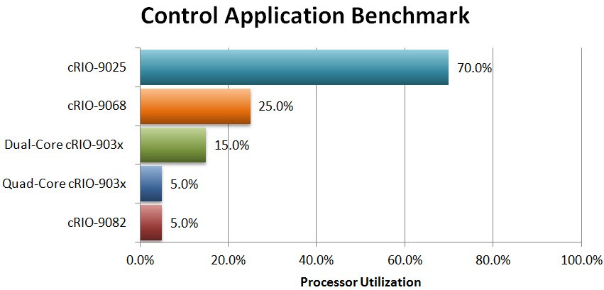
Figure 2: The processor usage required to run a control application that runs an 8 channel cubic spline trajectory generation algorithm of 1.5 kHz
The test was repeated with the Embedded UI option enabled for the CompactRIO controller; however, since this test does not stress the HMI portion of the LabVIEW FPGA Control on CompactRIO Sample Project, no significant changes in the CPU usage were observed.
Test 2 - Monitoring Application Throughput Benchmark
A common task in monitoring applications is to move data from I/O channels to the Real-Time processors for further processing, logging, or visualization. A simple test was created to reproduce this scenario and measure the CPU usage while varying the number of channels streaming data. Each channel carries 16-bit samples transferred at 100 kHz. No streaming to disk or online processing is included in the test.
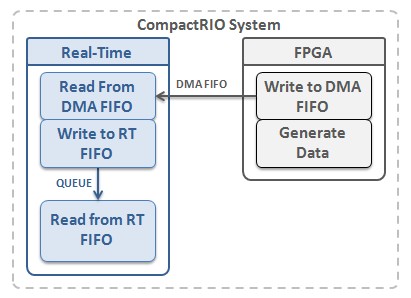
Figure 3: Architectural diagram of a simplified data streaming task for a monitoring application.
The figure below shows the result for streaming 100 channels at 100kHz. In this test we must be aware of the potential bottlenecks that arise from slight differences in hardware architectures. For instance, while both the cRIO-9068 and CompactRIO controller have 16 DMA channels implemented with different bus technologies, they still present notable theoretical maximum bandwidth rates: 320MB/s for the cRIO-9068 controller and 250MB/s for the CompactRIO controller. However, the CompactRIO controller can sustain a higher number of streams at a lower CPU utilization because its processor presents better performance.
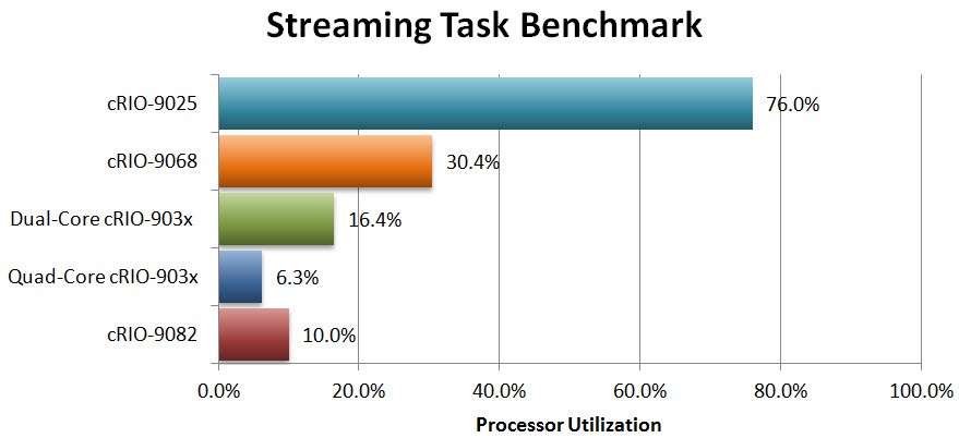
Figure 4: The processor usage required to stream 100 channels of 16-bit samples transferred at 100kHz per channel
Similar to the Control Application Performance test, the effect of the Embedded UI option on the CompactRIO controller is not relevant since the test does not stress the HMI. To observe the effects of the Embedded UI feature please review Test 3.
Test 3 - Complex Real-World Application Performance Benchmark
Perhaps the best way to fully exercise the features of the cRIO performance controller is through a test with a complex real-world application. Larger applications usually combine different types of common monitoring and control tasks including multiple processing loops with multi-rate control, data processing, streaming data from I/O channels, streaming to disk, communicating data across the network to a remote HMI, and performing non-time-critical health and status monitoring tasks.
A complex application featuring the tasks described above was implemented using common LabVIEW architectural components like RT FIFOs, timed loops, and network streams to coordinate and communicate between the various application components. Additionally, there is a task dedicated to publish data to front panel indicator at a high rate to fully stress the Embedded UI feature in cRIO performance controller.
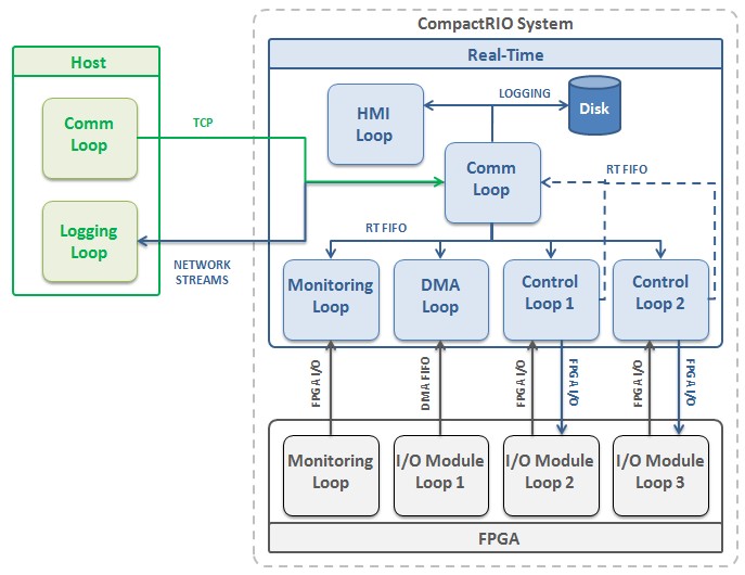
Figure 5: Architectural diagram of a complex real-world control and monitoring application
Using this application, the NI cRIO-9025 was able to achieve a maximum control loop rate of roughly 950Hz. At this rate, CPU usage was 91% while the dual-core performance controller only utilized 15% of available processor resources to achieve the same rate. This leaves a significant amount of available CPU resources to add additional application tasks, or the loop rate could be increased to speeds well over 2 kHz for this complex control and monitoring application. On the other hand, the quad-core variant showed very similar performance to the cRIO-9082 at all observed loop rates.
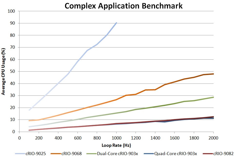
Figure 6: The CPU usage required to run a complex application with many common control and monitoring tasks at different control loop rates.
Effect of Embedded UI
The CompactRIO controller reduces system cost and complexity by implementing the local HMI with Embedded UI support. This is possible as this new controller incorporates the latest Intel Atom processor with accompanying graphics support providing a performant foundation for building both the control system logic and touch-enabled user interface with NI LabVIEW. To enable this consolidation, the LabVIEW development environment and the NI Linux Real-Time OS expose task prioritization to the developer to assign a higher priority to the control tasks over the HMI software tasks running in the same application.
In this approach the target’s resources are used both for the system control and to drive the graphics of the user interface. This reduces the system hardware cost and maintenance burden, simplifies the software development complexity, but does consume additional controller resources as compared to other display options.
To measure the impact of the Embedded UI on processor resources, Test 3 was modified to continuously stress the HMI by updating its components at high rates. The figure below shows the effect of using the Embedded UI feature with a very active user interface as observed in Test 3.
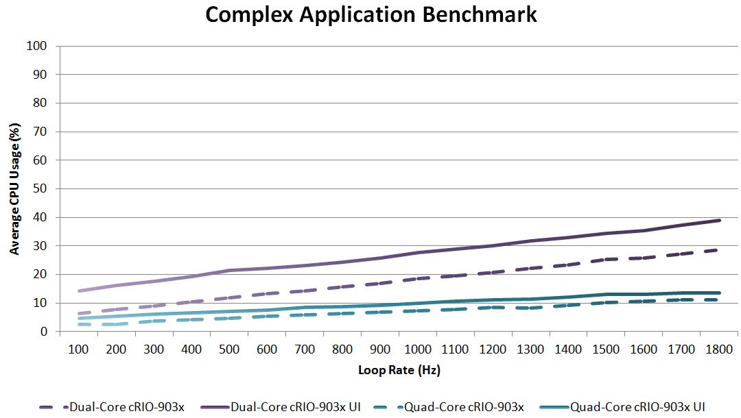
Figure 7: A constant CPU usage increase of roughly 3-10% can be observed when the Embedded UI feature is enabled and the user interface is updated at high rates.
When fully stressed, the use of the Embedded UI feature results in a CPU usage increase of roughly 10% for the dual-core performance controller and 3% for the quad-core performance controller. Similar to tests 1 and 2, the effect of the Embedded UI feature remains constant regardless of the variations in number of channels streamed.
To support the graphics capability of Embedded UI the Intel Atom SoC uses an on-board GPU to augment the CPU. The GPU communicates with the processor through frequent processor interrupt calls which takes some processing time away from the LabVIEW Real-Time application. Because of the high performance of the Intel Atom CPU this increase in variable processing time to update the GPU is sustainable with control loop rates below 6 kHz for the application benchmarked in test 3. To obtain higher loop rates while still utilizing Embedded UI either the GPU can be disabled or the LabVIEW control code can be shifted to the on-board FPGA as described in the links below.
For applications where these Embedded UI considerations could potentially compromise the performance of the system, please observe the following recommendations:
- Further task isolation is possible via processor core assignment of task execution in LabVIEW. Read more.
- Shift the LabVIEW control code to hardware logic in the on-board FPGA if further isolation and hardware reliability is required.
- Disable the GPU in the Intel Atom SoC to decrease jitter at the expense of CPU utilization.
Conclusions
Embedded applications perform an increasing number of functions such as motion control, data logging, vision acquisition, and HMI. The NI CompactRIO controller is a good fit to these applications due to the combination of technologies and unique features that accelerate development time and reduce system complexity and cost.
The CompactRIO controller presents a significant performance improvement over other families of controllers and it expands the range of targets compatible with key enabling technologies such as NI Linux Real-Time. The NI CompactRIO controller delivers flexible, powerful hardware and software technologies based on the LabVIEW RIO Architecture for a wide variety of embedded control and monitoring applications.
Through this series of benchmarks, the CompactRIO controller proved to have roughly 4-8 times better performance than existing offerings in comparable families of CompactRIO controllers such as the cRIO-9025. Additionally, the quad-core variant has very similar performance to the cRIO-908x.