Generating a Signal: Types of Function Generators, DAC Considerations, and Other Common Terminology
Overview
Learn about how signal generators generate analog signals and other topics such as types of signal generators, bit resolution, bandwidth, attenuation, digital gain, digital filtering, and analog filtering.
Contents
- Types of Signal Generators
- Digital-to-Analog Conversion Characteristics
- Attenuation and Digital Gain
- Filtering and Interpolation
- Summary
- Next Steps
Types of Signal Generators
The broad category of signal generators can include many different types of devices. At a higher level, there are two main groups: (1) signal generators, also called arbitrary/function generators and arbitrary waveform generators, and (2) logic sources, also known as pulse or pattern generators. Signal generators create waveforms with analog characteristics and logic sources generate digital waveforms that are commonly used to test computer buses. This article focuses on signal generators.
Function Generators
Function generators produce a limited number of predefined periodic waveforms at precise frequencies. More recent function generators employ a technology called direct digital synthesis (DDS), which gives the device the ability to produce the waveforms at precise frequencies. Function generators using DDS can change their output waveform frequency during generation with a short response time. To read more about DDS, refer to the Direct Digital Synthesis (DDS) white paper in the Instrument Fundamentals series. Function generators often have very limited memory size, because they store only a small amount of periodic waveforms. Common waveforms such as sine, square, pulse, ramp, and sweep are included in a function generator’s memory; however, depending on the device, there could be more or less waveform options available. Function generators are cost-effective devices for applications such as stimulusresponse testing, filter characterization, and clock source simulation, which require only periodic waveforms.
Arbitrary Function Generators
Arbitrary function generators (AFGs) are similar to function generators with one important additional capability: onboard memory space dedicated for a user-defined waveform. This gives you the capability to define a waveform, store it to the AFG onboard memory, and then output the waveform using DDS. Similar to function generators, AFGs also have predefined sets of waveforms stored on the device’s onboard memory that can be output using DDS. Therefore, AFGs are extremely valuable devices if you are working with the same kind of applications suited for function generators, but you benefit from defining a more unique waveform than the predefined waveforms from the vendor. Before purchasing, always verify your user-defined waveform fits on the device’s user-available memory.
Arbitrary Waveform Generators
Arbitrary waveform generators (AWGs) can produce the standard waveforms as well as large, complex, user-defined waveforms. Some AWGs also have the added capability of linking and looping combinations of waveforms to effectively produce sequences of waveforms to output. To output complex or sequenced waveforms, AWGs must use a large amount of onboard memory to store these waveforms. Therefore, if you plan to use a specific complex waveform for your application, make sure to purchase an AWG with enough memory to store the applicable waveforms. In addition to increased memory space, AWGs also employ a different clocking scheme than function generators or AFGs using DDS. An AWG’s clocking scheme allows the device to output points only in the order that they are placed in memory; therefore, they cannot change the frequency of output in a short time.
Digital-to-Analog Conversion Characteristics
Bit Resolution
The bit resolution, or vertical resolution, of a signal generator is defined by the resolution of the digital-to-analog convertor (DAC) used. A DAC can only produce an output waveform using discrete voltage steps, or levels. You can find the number of discrete voltage levels a DAC can produce by raising two to the power of the DAC resolution. Figure 1 demonstrates the difference of varying DAC resolutions by comparing a sine wave created by a theoretical 3-bit DAC to a sine wave created by a 16-bit DAC.
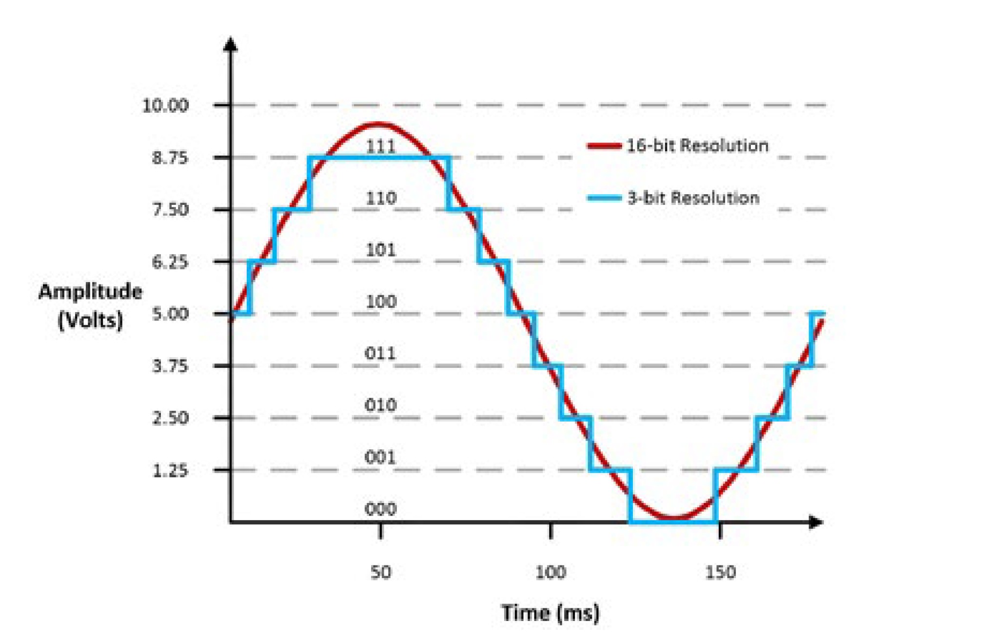
Figure 1: Differences of Two Different DAC Resolutions in Analog Signal Creation
Table 1 shows the number of discrete voltage levels each DAC can produce and Equation 1 shows how the number of discrete voltage levels for a DAC is calculated.

Equation 1: Calculating the Discrete Voltage Levels for a DAC
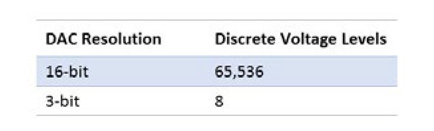
Table 1: Discrete Voltage Levels of 3-Bit and 16-Bit DAC
The 3-bit DAC can output only eight discrete voltage levels; therefore, if the DAC had a 0 V to 10 V signal range, it can produce voltages in only 1.25 V increments, as seen in Figure 1. The 16-bit DAC can produce voltages at 152.6 μV increments and that is why the signal appears much smoother. Equation 2 shows the general formula and how the voltage increment, or commonly referred to as code width, is calculated for the 16-bit DAC.
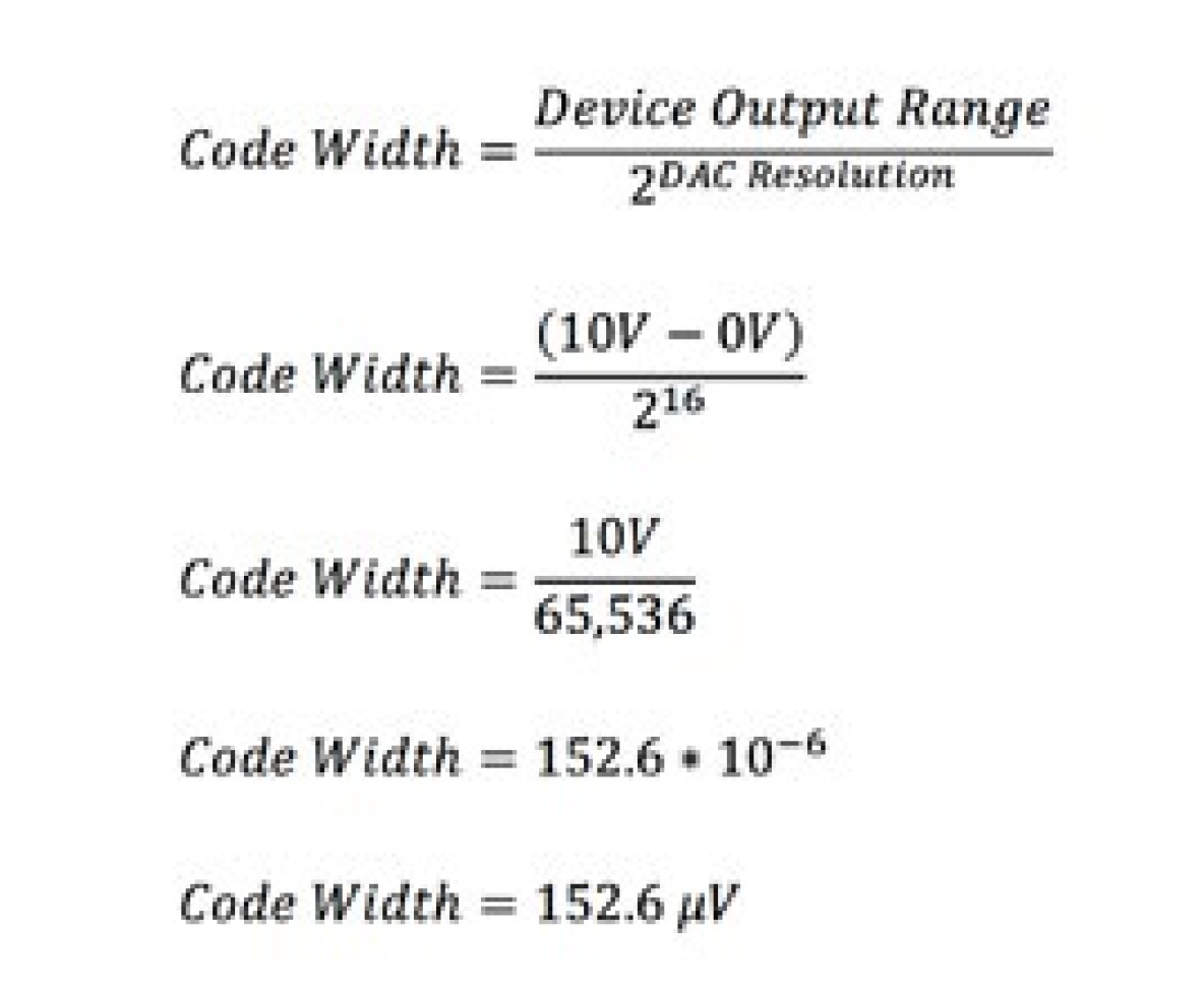
Equation 2: Code Width General Formula and Code Width Calculation Example for a 16-Bit DAC
Note that if you zoomed in to a small enough scale, the sine wave produced by the 16-bit DAC would also exhibit a stepwise appearance but with 152.6 μV increments.
Bandwidth
The bandwidth of an AFG or AWG describes the maximum frequency the device’s analog circuitry can output without significant attenuation. The maximum frequency for the bandwidth specification is defined as the frequency where a sinusoidal output signal is attenuated to 70.7 percent of the signal’s original amplitude. This frequency is also known as the -3 dB point on a bode plot.
The bandwidth specification determines the maximum frequency of sinusoidal output and other specifications such as overshoot and rise time for the instrument. This becomes critical when generating square waves or pulse signals with the signal generator. As seen in Figure 2, a signal generator with a higher bandwidth can produce square waves with smaller overshoot and faster rise times.
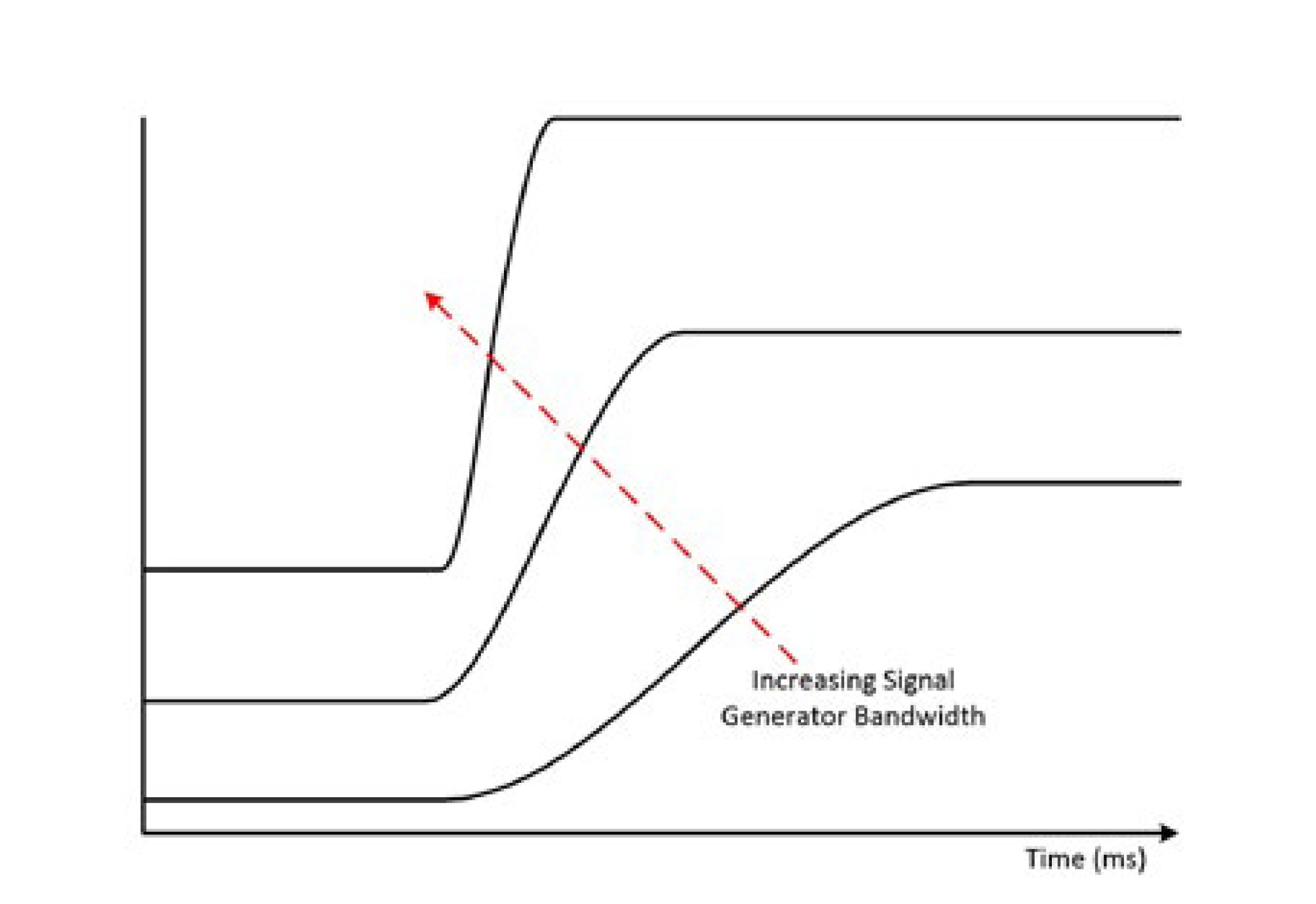
Figure 2: Higher signal generator bandwidth allows for a better representation of the signal. In this figure, the signal is a square wave.
Attenuation and Digital Gain
Signal generators are designed to produce waveforms at a variety of voltage ranges and they can switch between these voltage ranges quickly. Depending on the supported voltage ranges and how they are implemented, it is possible that a change in voltage range could require a relay switch to change the physical routing for a signal. This affects the output signal and a glitch may be observed. To accomplish this task, signal generators can employ the following techniques.
Attenuation
Attenuating the DAC output signal gives the signal generator the ability to alter the generated signal’s amplitude while using the dynamic range of the DAC. To illustrate this, consider a situation where a 16-bit DAC with a 0 to 10 V range is used but the wanted output signal ranges from 0 to 1 V. To produce the wanted output signal, the digital data is written to the DAC at the full 0 to 10 V range, and then the analog signal at the output of the DAC is attenuated 10x. This effectively decreases the voltage resolution to 15.26 μV because the full resolution of the 16-bit DAC was used. If the 0 to 1 V signal was produced by only writing digital words to the DAC that represented values between 0 to 1 V at the 0 to 10 V range, the voltage resolution would stay at 152.6 μV as shown in Equation 2. Although attenuation uses the full resolution of the DAC, it is often a slower technique because it involves switching combinations of resistor networks.
Digital Gain
Digital gain is a technique that involves multiplying the waveform digital data by a factor before that data reaches DAC. Because digital gain is applied during waveform generation while the digital data is transferred from the signal generator memory, the delay associated with applying digital gain is minimal in comparison to analog gain methods. However, the output resolution of the DAC is a function of digital gain, which means that only analog gain uses the full resolution of the DAC.
Filtering and Interpolation
To generate a signal with the proper frequency, the device update rate, or sampling rate, must be twice the maximum frequency component of the generated signal. Strictly following this criterion would leave you with only a generated signal with the correct frequency, but to generate the most accurate representation of the waveform shape, the DAC operation must be accounted for. DACs use a sample-and-hold technique, which introduces high-frequency images even in a highly oversampled waveform. The sample-and-hold output can be seen visually in Figure 3 in the time domain when a sinusoid is sampled at 20 times the sine wave frequency. The sample-and-hold output gives the stepped waveform appearance.
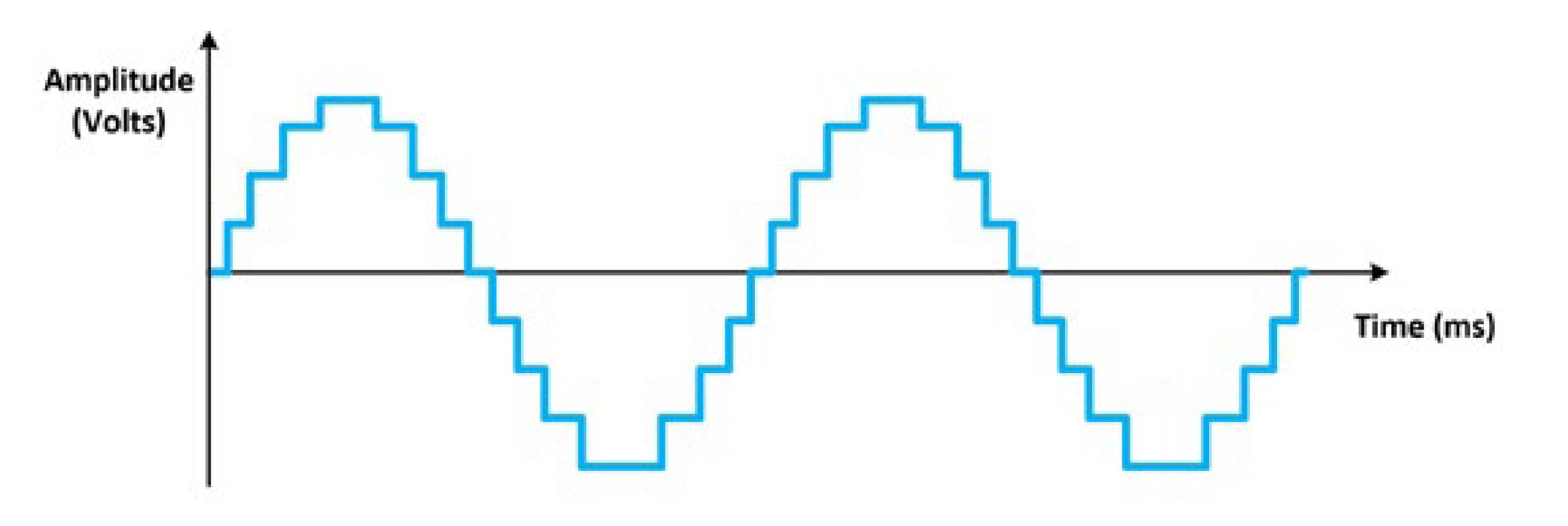
Figure 3: This time domain graph of the generated sine waveform showcases the sample-and-hold technique used by DACs.
The time domain signal still resembles a sine wave; however, inspection of the frequency domain reveals the high-frequency images created by the DAC. These images occur at integer multiples of the sampling rate plus or minus the fundamental tone. For example, a 20 MHz sine wave generated by a 100 MHz sample clock has images at 80 MHz, 120 MHz, 180 MHz, 220 MHz, and so on. Figure 4 shows the frequency domain of a generated sine wave with high-frequency images.
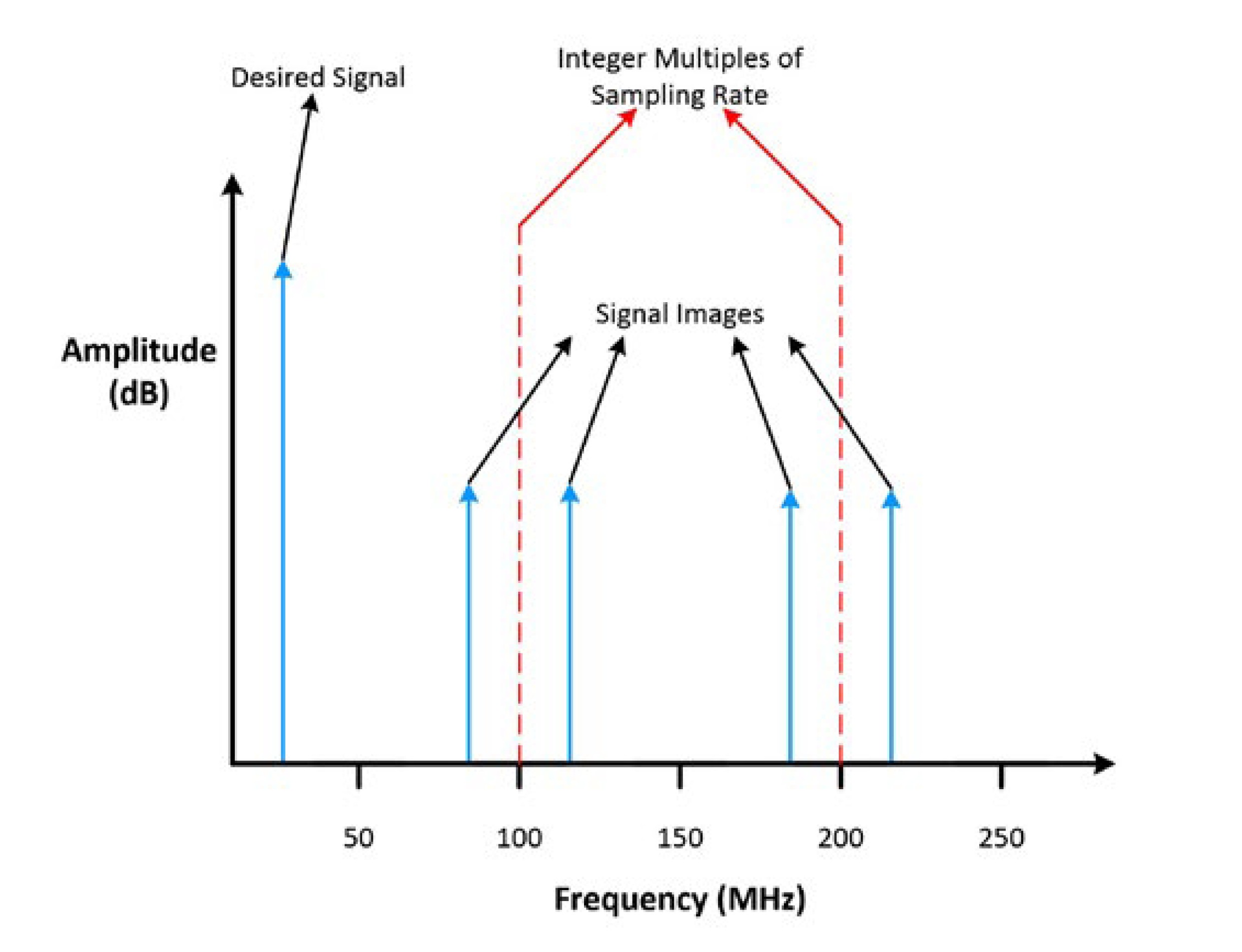
Figure 4: This frequency domain graph of the generated sine wave shows the high-frequency images.
Signal generators can use a combination of digital and analog filters to remove these images to create a more spectrally pure signal.
Digital Filtering and Interpolation
A signal generator can use a digital finite-impulse response (FIR) filter to provide points that interpolate between generated samples. This increases the effective sampling rate, which in turn alters the location of high-frequency images in the frequency domain. For an explanation of this concept, think of the original example of a 20 MHz sine wave generated by a 100 MHz sample clock. If the FIR filter interpolates the signal by 4x, you can now find the images using 400 MHz as the sample clock rate, thus producing images at 380 MHz, 420 MHz, 780 MHz, 820 MHz, and so on when they were originally, in Figure 4, at 80 MHz, 120 MHz, 180 MHz, 220 MHz, and so on. As Figure 5 below illustrates, interpolation does not eliminate spectral images, but it does shift these images farther from the fundamental tone.
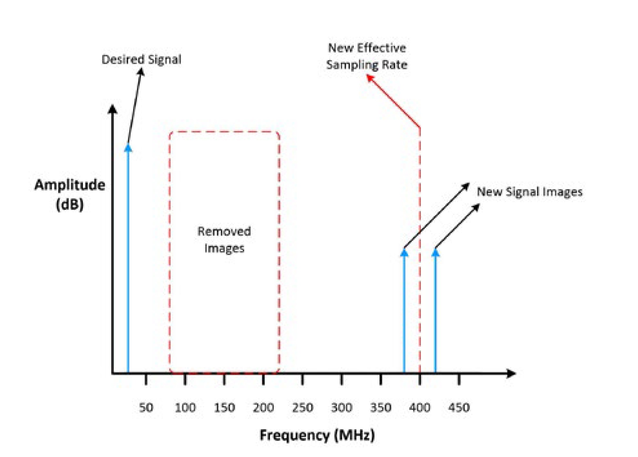
Figure 5: In this frequency domain graph of the generated sine wave, the digital filtering has moved the high-frequency images further away from the fundamental tone
Analog Filtering
To produce the most spectrally pure signal, an analog filter can be applied after the interpolated signal. Because the digital FIR filter has pushed the high-frequency images farther from the fundamental tone, the requirements for the analog filter have relaxed. The analog filter does not need as steep a cut-off frequency, which would have given the circuit poor passband flatness. As seen in Figure 6, after the digital FIR filter and analog filter are applied, the high-frequency images are removed from the frequency domain.
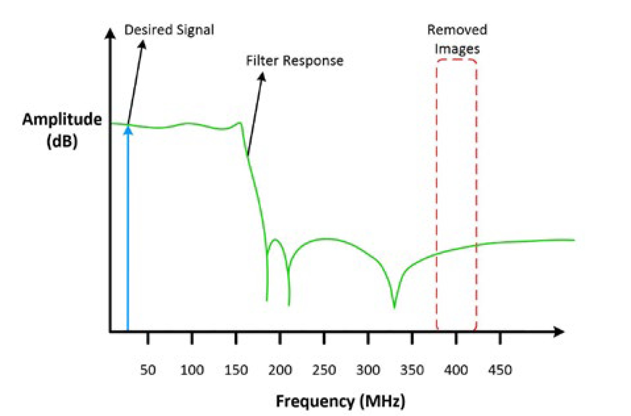
Figure 6: This is the frequency domain graph of the generated sine wave after digital and analog filtering are applied.
Because the digital FIR filter and analog filter have effectively removed the high-frequency images, you can inspect the sinusoid waveform, in Figure 7, in the time-domain once again.
Figure 7: This is the time domain graph of the generated sine waveform after digital and analog filtering.
Notice the stepped waveform appearance created by the high-frequency images is removed and the generated sinusoid signal appears to be a more pure sinusoid waveform compared to the sinusoid in Figure 1.
You have now seen how bit resolution, bandwidth, attenuation, gain, and filtering affect the output signal from a signal generator. While looking at the specifications sheet of your signal generator, make sure to keep these specifications in mind and match them to the requirements of your application.
Summary
- Function generators produce a limited and predefined set of periodic waveforms at precise frequencies.
- Arbitrary function generators (AFGs) have the same capabilities as a function generator with the added benefit that you can use the accessible onboard memory to add a userdefined waveform.
- Arbitrary waveform generators (AWGs) produce the standard waveforms as well as large, complex, user-defined waveforms and they do this by using a much larger onboard memory in comparison to function generators and AFGs.
- The bit resolution, also vertical resolution, of a signal generator defines the number of discreet voltage levels the DAC can produce.
- Bandwidth describes the range of frequencies a signal generator can output. It is defined by the frequency at which a sinusoidal input signal is attenuated to 70.7 percent of its original amplitude, which is also known as the -3 dB point.
- Attenuation is a technique that alters the generated signals amplitude without sacrificing the dynamic range or losing digital bits of representation.
- Digital gain is a technique that involves multiplying the waveform digital data by a factor before the DAC. This gives the generated signal the ability to change amplitude nearly instantly; however, it may not use the full resolution of the DAC.
- Interpolation and analog filtering can be used to increase the effective sampling rate and remove the high-frequency images of a signal generated by a DAC.
Next Steps
- Learn about NI PXI Waveform Generators for automated characterization, validation, and production test
- Find the right analog signal generator
- Configure your test system using our online PXI advisor