Explore Circuit Behavior Using Simulation-Driven Instruments in NI Multisim
Overview
This article examines the three different types of simulation-driven instruments and how you can use these instruments to drive circuits, make measurements, probe, and troubleshoot a circuit.
Contents
- Introduction to Simulation-Driven Instruments
- Types of Simulation-Driven Instruments
- Multisim Instruments
- LabVIEW Custom VIs
- NI-ELVISmx Instruments
Introduction to Simulation-Driven Instruments
In addition to the components and wires used to capture a circuit, NI Multisim software contains a variety of simulation-driven instruments that wire into the schematic just like you connect a real instrument on the bench. These simulation-driven instruments, like their real-world counterparts, are fully interactive so you can change their settings while running a simulation and instantly see new results.
Simulation-driven instruments help you take advantage of the full power of simulation without having to be an expert in SPICE syntax. When you press a button on an instrument, an appropriate simulation command is automatically issued and results are immediately displayed on that instrument's user interface. You can save instrument settings and simulation results with the circuit file and resize the faceplates of instruments to adjust to different screen resolutions and presentation modes.
With Multisim, you can place simulation-driven instruments from the Simulate»Instruments menu or directly from the Instruments toolbar as seen below.
Simulation-driven instruments have three distinctive views to each instrument, which allows for selection, placement, wiring, setting configuration, data visualization, and so on.
| Type | Description | View |
| Icon |
| |
| Symbol |
|  |
| Panel | Allows the user to interact with the instrument by
|  |
You can show or hide the instrument panel by double-clicking on the instrument's symbol. The instrument panel is always drawn on top of the main workspace so that the parameters are not hidden. You can place the instrument panel wherever you wish on your desktop and resize it to account for different screen resolutions and presentation modes. When you save your circuit, the instrument panel location and hide/show status are stored with the circuit. Also, any data contained in the instrument is saved, up to a maximum size.
Types of Simulation-Driven Instruments
The three distinct types of simulation-driven instruments are Multisim instruments, LabVIEW custom VIs, and NI-ELVISmx instruments. All of these instruments offer the following key capabilities:
- Adjust settings while the simulation is running
- Rewire terminal while simulation is running
- Use multiple instances of the same instrument in one circuit
- Save instrument settings and display data with the circuit file
- Populate displayed data in the Grapher view
- Resize instrument panel to account for screen resolution or presentation mode
- Easily export displayed data in TXT, LVM, and TDM format
Multisim Instruments
Multisim instruments are simulation-driven instruments that are innate in the Multisim environment. You can group them into six categories to better organize them:
- AC and DC instruments
- Digital and logic instruments
- RF instruments
- Simulated vendor instruments
- Measurement probes
- LabVIEW VIs
Note: Pictures and icons seen in this document are reduced in size and quality.
AC and DC Instruments
Name | Function | Icon | Symbol | Panel |
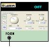
Function Generator |
| 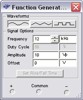 | ||
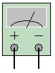
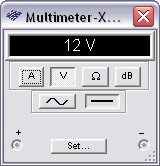
Multimeter |
| |  | |
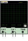
2-Channel Oscilloscope |
| 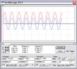 | ||
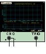
4-Channel Oscilloscope |
| 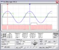 | ||
Wattmeter |
| 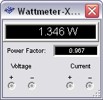 | ||
| IV Analyzer |
|  | 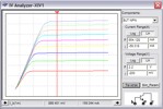 | |
Frequency Counter |
| 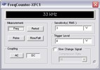 | ||
Bode Plotter |
| 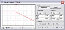 | ||
Distortion Analyzer |
| 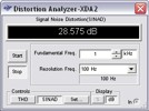 |


Digital and Logic Instruments
Name | Function | Icon | Symbol | Panel |
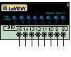
Logic Analyzer |
| 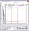 | ||
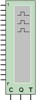
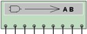
Logic Converter |
| | 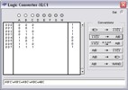 | |
Word Generator |
| 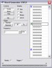 |
RF Instruments
Name | Function | Icon | Symbol | Panel |
Spectrum Analyzer |
| 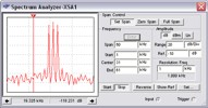 | ||
Network Analyzer |
| | 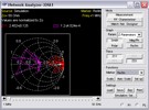 |


Simulated Vendor Instruments
Name | Function | Icon | Symbol | Panel |
Agilent Waveform Generator |
| 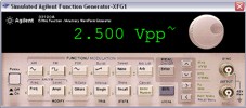 | ||
Agilent DMM |
| 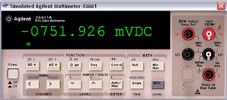 | ||
Agilent Oscilloscope |
| 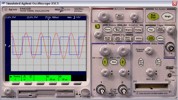 | ||
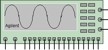
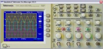
Tektronix Oscilloscope |
|
|


Measurement Probes
Name | Function | Icon | Symbol | Panel |
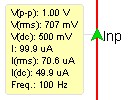
Static Measurement Probe |
|
|
| |
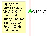
Current Probe |
| Use standard simulated instruments to display data
|


Instruments Based on LabVIEW
Name | Function | Icon | Symbol | Panel |
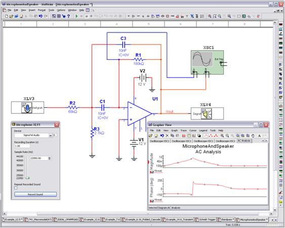
LabVIEW Microphone |
| 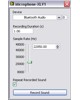 | ||
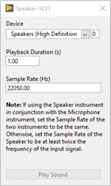
LabVIEW Speaker |
| |
| |
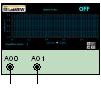
LabVIEW Signal Analyzer |
| 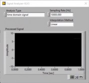 | ||
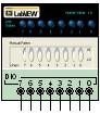
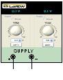
LabVIEW Signal Generator |
| 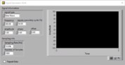 | ||
LabVIEW Streaming Signal Generator |
| 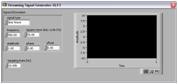 | ||
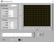
LabVIEW BJT Analyzer |
|
| ||
LabVIEW Impedance Meter |
|
|
LabVIEW Custom VIs
Extend your simulation and analysis capabilities beyond the instrumentation in Multisim with the creation of custom VIs using the LabVIEW graphical development environment. VIs that you create using LabVIEW can take advantage of the full functionality of the LabVIEW development system, including data acquisition, instrument control, and mathematical analysis. For example, you can create the following kinds of VIs:
- A virtual instrument that acquires data from the real world using an NI data acquisition device or modular instrument. Multisim then uses that data as a signal source for circuit simulation.
- A virtual instrument that displays simulation data simultaneously with multiple measurements (running average and power spectrum, for example) made from that simulation data.
LabVIEW VIs can be input instruments, output instruments, or input/output instruments.
Input instruments receive simulation data for display or processing.
Output instruments generate data to use as a signal source in simulation.
Input/output instruments both receive and generate simulation data.
You can install these VIs created and customized in LabVIEW into Multisim, and they appear in the LabVIEW Instruments toolbar. For more information on building a LabVIEW VI and LabVIEW VI installation, view the Multisim Help file.
NI-ELVISmx Instruments
By integrating NI ELVIS and Multisim, you can correlate simulated data with real-world measurements. NI Educational Laboratory Virtual Instrumentation Suite (NI ELVIS) is an NI hardware design and prototyping platform that contains 12 of the most commonly used instruments into one integrated platform that connects to your computer through a Hi-Speed USB connection.
Inside the Multisim environment, you can access eight of these instruments. With one click of the mouse, you can switch from simulated data generated by the Multisim SPICE simulation engine and the signals acquired from the hardware. This helps engineers prototype faster and educators reinforce theory with real-world signals.
Name | Function | Icon | Symbol | Panel |
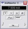
NI-ELVISmx Digital Multimeter |
| 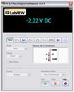 | ||
NI-ELVISmx Function Generator |
| | 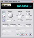 | |
NI-ELVISmx Oscilloscope |
| 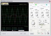 | ||
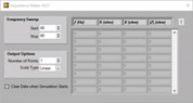
NI-ELVISmx Dynamic Signal Analyzer |
| 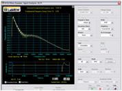 | ||
NI-ELVISmx Digital Reader |
| 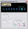 | ||
NI-ELVISmx Digital Writer |
| 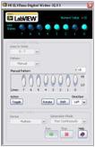 | ||
NI ELVISmx Arbitrary Waveform Generator |
| 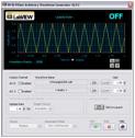 | ||
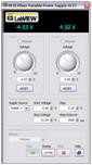
NI-ELVISmx Variable Power Supply |
|  |