Best Practices for Building and Maintaining PXI Systems
Overview
PCI eXtensions for Instrumentation(PXI) is a test, measurement, and control platform designed for demanding applications that require maximum uptime and a high level of reliability. The PXI specification ensures this with requirements such as a rugged Eurocard form factor and forced-air cooling. Moreover, PXI products from NI are designed, manufactured, and tested with the goal of delivering the highest quality products for the most demanding applications.
As an example of NI design standards, Flotherm modeling is used during new chassis development to optimize cooling within the chassis card cage and power supply. During the development testing stage, empirical testing is performed to ensure these cooling levels have been achieved. Additionally, PXI chassis, controllers, and modules from NI undergo highly accelerated life testing (HALT) during development testing to ensure product design margins and reliability. These, along with the many other practices that NI employs during design, manufacturing, and test, result in PXI products of the highest quality and reliability.
As a result, NI has achieved the highest standards in both the product's quality and reliability specifications like the mean time between failures (MTBF). There are also tens of thousands of systems that have been deployed into the most demanding applications around the world, such as nuclear power plant inspection. However, all electronic devices have some failure rate and not even the most reliable electronic systems (medical monitoring equipment, data servers in financial institutions, and so on) are immune to failures, rare as they may be. To help you reduce the risk and maximize the uptime of your PXI system, this white paper presents best practices to follow during assembly, deployment, and maintenance. Additionally, the techniques discussed here minimize the downtime of your PXI system if you do experience a failure.
Contents
- Best Practices Check List
- Assembling Your PXI System
- Deploying Your PXI System
- Using and Maintaining Your PXI System
- Next Steps
Best Practices Check List
| Assembly | |
|---|---|
| Select components that meet or exceed temperature requirements | Required |
| Install filler panels in unused or empty chassis slots | Required |
| Perform a power budget to ensure adequate power is available for all components | Recommended |
| Install slot blockers in unused or empty chassis slots | Recommended |
| Set fan speed selector to HIGH on applicable chassis | Recommended |
| Use 24/7 operation hard drives if the system will exceed 8/5 operation | Recommended |
| Use solid-state hard drives if shock and/or high vibration will be present | Required |
| Plan for spares and/or redundancy if downtime for maintenance is not acceptable | Recommended |
| Select the appropriate NI System Assurance Program for system assembly, test and service | Recommended |
| Use adequate controller memory (RAM) | Recommended |
| Deployment | |
| Verify that the ambient temperature is within component specifications | Required |
| Use recommended rack-mounting guidelines if applicable | Recommended |
| Install chassis such that cooling clearances are met | Required |
| Connect chassis to an appropriate ground | Required |
| Use a surge protector, power conditioner, or UPS if power quality/reliability is in question | Recommended |
| Use ruggedized enclosures if environmental conditions exceed component specifications | Recommended |
| Use and Maintenance | |
| Employ good programming design practices | Recommended |
| Follow the proper system power down procedure | Required |
| Clean chassis fan filters at a minimum interval of six months (if applicable) | Required |
| Perform a complete system cleaning periodically | Recommended |
| Monitor system conditions periodically | Recommended |
| Calibrate instruments at required intervals | Required |
| Stock spare components | Recommended |
| Be aware of technical support resources | Recommended |
Assembling Your PXI System
When assembling a PXI system, it is important that you select the correct components. A PXI system is composed of three basic components – chassis, controller, and modules. These components must be selected not only based upon the measurement and control performance, but also upon the environment in which the system will be deployed, extended-operation requirements, and power requirements.
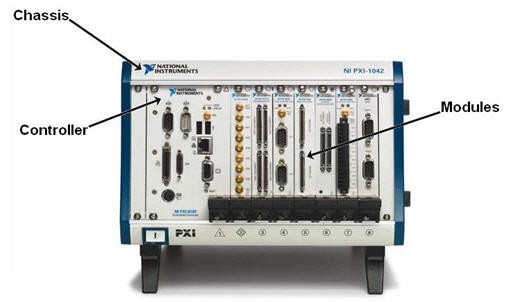
Figure 1. PXI system components should be selected based upon measurement and control performance, the environment in which the system will be deployed, extended-operation requirements, and power requirements.
Deployment Environment
The environment in which your PXI system is deployed is characterized by environmental conditions such as temperature, humidity, shock, vibration, and altitude. You should verify that the components that you plan to use have specifications that meet or exceed these environmental conditions. Temperature, shock, and vibration are most often the environmental conditions that require consideration.
PXI is an industrial platform with extended temperature, shock, and vibration specifications. If your PXI system is operated in an environment with a minimum ambient temperature less than 5 C and/or a maximum ambient temperature greater than 50 C, you must select a chassis and embedded controller with an extended operating temperature range. These chassis and controllers include components designed for reliability in the low- and high-temperature extremes. For example, an extended-temperature embedded controller includes a hard drive with temperature specifications that exceed those of standard commercial hard drives.
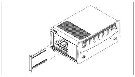
Regardless of the ambient temperature of the environment in which your PXI system is deployed, a few simple techniques can improve the cooling performance of your chassis. First, you must install filler panels, which are provided with NI chassis, in unused or empty slots. The temperature specifications of the chassis and modules require the usage of filler panels in unused slots.
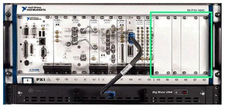
Figure 2. Filler panels are required for cooling in unused or empty PXI chassis slots.
Another technique that you can use to improve the cooling performance of your chassis is the installation of slot blockers. A PXI system is rated to operate up to its specified maximum operating temperature, but if you desire improved cooling performance (for example, lower chassis and module component temperatures), you should consider using PXI slot blockers, which improve air flow through modules by reducing air flow bypass that can occur in unused chassis slots. This improved air flow can reduce component temperatures within the chassis and modules.
Figure 3. Slot blockers can improve the cooling performance of PXI chassis by reducing air flow bypass.
Finally, many NI chassis include a fan-speed selector switch on the rear panel of the chassis. For maximum cooling performance select HIGH. For quieter operation, select AUTO. When set to AUTO, the fan speed is determined by chassis intake air temperature.
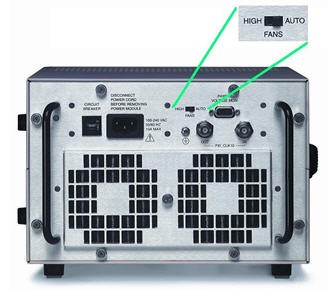
Figure 4. For maximum cooling performance, set the fan-speed selector to HIGH on applicable PXI chassis.
If your PXI system operates in an environment with shock and/or vibration, using a standard rotating media hard drive in your controller may not be appropriate because shock and/or vibration can cause the hard drive head to make contact with and damage the media. Because a solid-state hard drive does not include any moving parts, it can tolerate exposure to higher levels of shock and vibration. You should consider using a solid-state hard drive in your PXI system in this type of environment. NI can install a solid-state hard drive in your embedded controllers in the factory and deliver it to you ready for deployment.
Duration of Extended Operation
If your PXI system is deployed into an application that requires continuous operation for extended periods of time up to 24 hours a day, 7 days a week (often referred to as 24/7 or high-duty-cycle operation), it is important that you select components designed for this type of usage. Again, since PXI is an industrial platform, the majority of PXI products from NI have been designed for extended operation. The one component that requires consideration is the controller.
Standard hard drives are designed to be powered on for eight hours a day, five days a week. Applications that require extended operation require a hard drive designed for these extended power on hours. Additionally, these applications may or may not subject the hard drive to a high duty cycle, which refers to the percentage of maximum sustained throughput. A standard hard drive is designed for a 20 percent duty cycle. NI offers 24/7 embedded controllers with hard drives designed for use in applications that require extended operation up to 24/7.
In addition to selecting an appropriate hard drive, using adequate system memory (or RAM) in your controller is also important if your PXI system is deployed into an application that requires extended operation. If the programs running on your controller require more memory than is available, the operating system uses the hard drive as virtual memory. This is referred to as hard drive paging, and if it takes place continuously, the hard drive can experience a decreased operating lifetime. For applications that require continuous operation for extended periods of time, you should verify that your controller has enough memory to fulfill the requirements of your software.
Another consideration for PXI systems that are operating continuously for extended periods of time and downtime for maintenance is unacceptable, is the addition of redundancy to the system. The redundancy can be as complete as having two identical systems where the backup system is designed to begin operating if the primary system fails. Alternatively, the redundancy can be at the component level. For example, by selecting a chassis that has multiple fans, such as the NI PXI-1042, if a single fan fails, the system may be able to continue operating (dependent upon the ambient temperature).
Using RAID (redundant array of independent disks) hard drive configurations is another way of adding component-level redundancy to your PXI system. With a RAID-1 (mirrored) configuration, each piece of data is written to two (or more) hard drives. In a two-drive RAID-1 configuration, if one hard drive fails, the system can continue operating using the functional hard drive without any system downtime. PXI and PXI Express rack-mount controllers from NI can be configured with a two-drive RAID-1 array.
Power Requirements
A key factor to consider when configuring your PXI system is total power consumption. This ensures proper system performance and guarantees the safety of the hardware. A power budget takes into account the capacity of the power supply in the PXI chassis at a given temperature, as well as the power requirements of the controller and modules within the chassis. Efficiency is also a key element of the budget to compensate for real-world performance of electrical equipment and variations with time.
There are three steps involved in determining the power budget for your PXI system. First, complete an analysis of the power supply and its specifications. You must understand how much power can be provided by the supply being used. Next, determine which controller and modules to use in the PXI system. Each element of the system affects the amount of power consumed. Finally, you should know the power consumption of the PXI chassis and its components. Each of these hardware components plays a part in accurately calculating the power budget for your PXI system. The tutorial Determining the Power Consumption of a PXI System provides step-by-step instructions for calculating a power budget for your system.
System Configuration Services
NI offers system configuration services designed to simplify the assembly of your PXI system. NI system assurance programs provide several options, which allow you to customize your system configuration. System assurance programs help you get your PXI system up and running out of the box and reduces the total cost of ownership for your system. Based upon your specifications, NI technicians install your modules in your chassis, plus any memory upgrades, NI application software, and any required driver software on your embedded controller. The NI Basic System Assurance Program delivers the system with the latest versions of software installed, while the NI Standard System Assurance Program and the NI Premium System Assurance Program provide the flexibility to choose previous versions of software or to mix and match versions to customize your software configuration.
NI performs a system-level test on all PXI systems configured with a system assurance program to verify that the software is installed correctly and that the modules are fully functional. PXI systems installed and configured through the standard and premium programs also include custom system documentation such as a pass/fail report from the system-level test, a platform specific recommended maintenance guide and printed calibration certificates for all measurement modules. In addition, the hard drive recovery image, which is included with every NI embedded controller, is customized to your exact software configuration. The standard program also provides three years of warranty and calibration coverage to help you maintain your system once it is deployed, and the premium program extends that coverage to five years for systems with longer life-cycles.
Deploying Your PXI System
After you have assembled your PXI system, having considered factors such as the environment in which the system will be deployed, the duration of continuous operation, and power requirements, you are now ready to deploy your system. PXI systems, because of the diversity of applications they solve, are deployed into a wide variety of rack-mount, benchtop, and embedded environments. Regardless of where you deploy your PXI system, you must consider the ambient temperature of your system, cooling clearances, power quality and reliability, and ruggedness.
Ambient Temperature
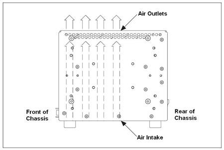
The ambient temperature of a PXI system is defined as the temperature at the chassis fan inlet (air intake). The air intake on a NI chassis is located either at the rear or bottom. A simple room temperature measurement is a good estimate of ambient temperature, but may not be the actual ambient temperature of your PXI system. For example, heat dissipation from surrounding equipment, such as the equipment in a 19 in. rack, can increase the ambient temperature.
Figure 5. The ambient temperature of a PXI system is defined as the temperature at the air intake, which can be on the rear or bottom of the chassis.
If your PXI system consistently has an ambient temperature above its maximum specification, it may ultimately lead to measurement inaccuracy, system shutdown, or premature system failure. Most often, ambient temperature is a concern for rack-mount deployments. If your PXI system is deployed in a rack, there are several guidelines that should be considered:
- Place high-power units within the rack above the PXI system(s) where possible.
- Use racks with open sides and/or rear panels.
- Use fan trays within the rack, including at the top and bottom of the rack, to increase overall air flow, which results in reduced ambient temperatures within the rack.
- Use other methods that result in lower ambient temperatures within the rack.
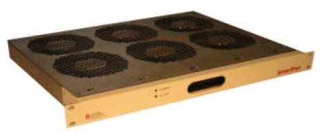
Figure 6. Using fan trays within a rack increases overall air flow and results in reduced ambient temperatures. (Image courtesy of Control Resources Incorporated)
Cooling Clearances
In addition to ensuring that the ambient temperature of your PXI system is within the specifications for all of the system components, it is vital that you provide adequate cooling clearances for your chassis so that the required chassis air flow is achieved.
Figure 7. PXI chassis must be installed such that the specified cooling clearances are met.
Your chassis must be installed such that the cooling clearances meet the specifications stated in the user manual. A typical example for an NI PXI chassis with a rear air intake and top/side exhaust, would be to provide a minimum of 76.2 mm (3 in.) of clearance from the air intake on the rear of the chassis and 44.5mm (1.75 in.) of clearance above and on the sides of the chassis. The figure below shows an example of two NI 18-slot chassis with the required 1.75 in. of clearance above each chassis.
Figure 8. An example of two NI PXI-1045 18-slot chassis rack-mounted with the required 1.75 in. (1U) of cooling clearance above each chassis.
Power Quality and Reliability
The power that you provide to your PXI system should be free of any spikes and noise that could degrade performance, reduce operating lifetime, and/or cause damage and failures to electronic equipment. Your PXI chassis must be connected to an appropriate ground either through the power cord or the chassis grounding screw on the rear of the chassis. You can use a surge protector if power spikes are a possibility and/or a power conditioner to improve the quality of noisy power. Additionally, you should consider using an uninterrupted power supply (UPS) if your PXI system receives power from an unreliable source.
Extended Ruggedness
If your PXI system is deployed in an environment with conditions, such as temperature, humidity, shock, and vibration, that exceed the specifications for the system components, it is often possible to install the system in a rugged enclosure that protects the system. To overcome temperature and humidity extremes, you can install your PXI system in a sealed enclosure that includes a heater, air conditioner, or heat exchanger. An enclosure with shock mounts can be used to overcome shock and vibration extremes.
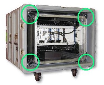
Figure 9. Rugged enclosures can be used for PXI systems that require extended ruggedness. This example is an RF record/playback system from NTS.
Using and Maintaining Your PXI System
Once you have deployed your PXI system, it is important that you use and maintain it properly. If you are not be the only operator of the system, you should educate the other operators on proper use and maintenance of the system. Failure to do so can lead to easily avoidable measurement errors or downtime.
Software Architecture
Using your PXI system properly begins with implementing a software architecture that eliminates unnecessary access to hardware that can artificially reduce operating lifetime. One example is designing your application so that data is written to and read from the hard drive only when necessary. In a data-logging application, it may make sense to buffer multiple data points in an array in memory and write them to a file on the hard drive when the buffer is full as opposed to writing each point to the file immediately after it is acquired.
Software Recovery and Backup
Many problems that appear to point to hardware failure are actually associated with software. For example, after deployment, you could install a piece of software (application, driver, and so on) on your PXI system that has a conflict with the driver for one of your PXI modules. Because this module has functioned properly in the past, and you have made no changes to your system directly associated with this module, you could reason that the module is malfunctioning. Another example is your PXI controller being infected by a virus. If the virus caused your controller to randomly crash, and you were not aware of the virus, it would seem that your controller is malfunctioning.
It is important to verify that you are not facing a software problem before deciding that your hardware has malfunctioned and returning it to NI to be repaired. If you determine that your PXI system has a software problem, being able to take advantage of recovery software can significantly reduce downtime. All NI Windows-based embedded controllers include hard drive-based recovery images and software. When you receive the embedded controller from the factory, it has a separate partition on the hard drive that includes a complete back-up image. You can re-image your embedded controller back to the factory image at any time without needing a CD, secondary hard drive, network connection, and so on. Moreover, you initiate the recovery process during boot before Windows has loaded, so even if your embedded controller cannot boot into Windows you can still recover the factory image.
The recovery software that is included on NI embedded controllers also gives you the ability to create custom backup images that can be stored on external or secondary hard drives, such as USB drives, and used as the recovery image instead of the factory image. After your PXI system is completely assembled and tested, you could create a custom backup image that you can use for recovery if you experience software problems after deployment.
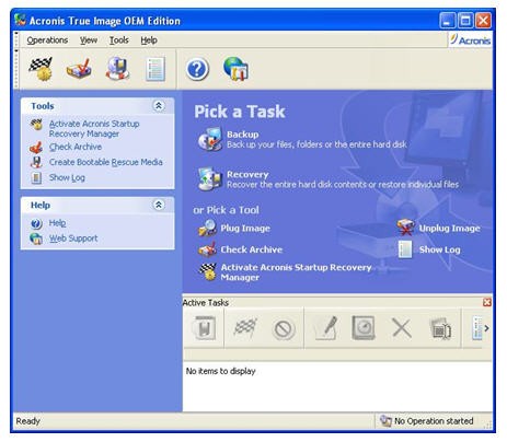
Figure 10. With recovery software, you can restore you PXI systems to a known-good state and reduce downtime.
System Power Down
If your PXI system uses a general-purpose operating system, such as Microsoft Windows, it is important that you follow the proper power down procedure. With a PXI chassis, such as the NI PXI-1045, after you have instructed the operating system to shut down, you receive a message on your monitor informing you that “It is now safe to shut down your computer.” At this point, you can power down your system using the chassis power switch. With a PXI Express chassis such as the NI PXIe-1062Q, the chassis automatically powers down by default after instructing the operating system to shut down. If you do not follow the proper power down procedure for your system, your controller’s hard drive experiences avoidable wear.
Cleaning Chassis Fan Filters
You must clean the chassis fan filters located at the air intake at a maximum interval of six months. Depending on the amount of use and ambient dust levels in the operating environment, the filters may require more frequent cleaning. A good practice is to clean the filters whenever they become visibly dirty. Dirty fan filters can dramatically reduce the cooling performance of your chassis. The NI manufacturing facility in Austin, Texas experienced an 8 to 10 °C reduction in internal temperatures within certain chassis used for functional test after implementing a schedule for cleaning the fan filters. Refer to your chassis operating manual for cleaning instructions. If desired, you can replace the fan filters. Refer to your chassis operating manual for ordering information.
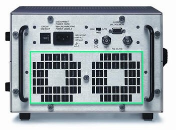
Figure 11. Chassis fan filters located at the air intake must be cleaned at a maximum interval of six months.
Cleaning Other System Components
Periodic cleaning of your entire PXI system increases reliability, especially if it is deployed in a dusty environment. Refer to the operating manuals for your chassis, controller, and modules for complete external and internal cleaning instructions.
Monitoring System Conditions
System conditions can change over time. The most common example of this is the ambient temperature of your PXI system rising. Many factors can cause this change in ambient temperature – for example, adding new equipment to the rack where your PXI system is deployed. Regardless, it is a good practice to periodically monitor the ambient temperature of your PXI system. Many of NI embedded controllers have internal temperature sensors that can be monitored programmatically. The example program Measuring the Temperature of Your PXI Embedded Controller demonstrates this. However, since the ambient temperature of your PXI system is measured at the chassis air intake, the measurement of the controller temperature is for reference only. You can do this manually or automate it by integrating the measurement into your PXI system.
Another system condition that can change over time is the health of your controller’s hard drive. It is good practice to periodically monitor the health of the hard drive with hard drive diagnostic software. NI provides a hard drive diagnostic tool for use with PXI and PXI Express embedded controllers.
Calibration
The accuracy of the electronic components used in all instruments drift some amount over time. The effects of time in service as well as environmental conditions add to this drift. As time progresses, changes in component values cause calibrationgreater uncertainty in your measurements. To resolve this issue, the instruments in your PXI system must be calibrated at regular intervals. Maintaining properly calibrated instruments reduces measurement errors, improves consistency between measurements, and provides you assurance that you are making accurate measurements.
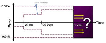
Figure 12. Calibrating instruments resolves inaccuracies that accumulate over time.
External calibration is the comparison of instrument performance to a standard of known accuracy. The result of an external calibration may be documentation showing the deviation of a measurement from the known standard, but most often it also includes adjusting the measurement capability of the instrument to ensure that its measurement accuracy is within vendor-provided limits. To have your PXI instruments from NI externally calibrated, you can send them back to NI, send them to a calibration or metrology laboratory, or use the external calibration capabilities at your facility (if available). Complete calibration resources are available on the Calibration Solutions from NI page.
In addition to external calibration, many PXI instruments from NI include self-calibration functionality. Instruments that offer self-calibration include hardware resources such as precision voltage references so you can quickly calibrate the instrument without removing it from the chassis or connecting it to external calibration hardware. Self-calibration is not a replacement for external calibration, but it does provide a method of improving instrument measurement accuracy between external calibration intervals.
Integrated Troubleshooting Resources
PXI products from NI include numerous integrated features that aid in troubleshooting. For example, most modules include the ability to perform an automated self test of the module’s functionality. Many of the chassis also include a power switch with an integrated LED that visually indicates the operating condition of the chassis. The four states are the following.
- If the power switch LED is steady green (not flashing), the chassis is powered on and operating normally.
- If the power switch LED is flashing green, the air-intake temperature has exceeded the chassis operating range.
- If the power switch LED is flashing red, the power supply outputs are not within voltage regulation requirements.
- If the power switch LED is steady red, the chassis fans are not operating properly.
Many PXI system problems are misdiagnosed as faulty hard drives when the actual problem is due to software, file corruption, file system corruption, or a virus. Many hard drive vendors provide hard drive diagnostic tools that determine if an actual hard drive failure has occurred. These tools can save you costly troubleshooting time and should be used before returning the hard drive, PC, or controller repair. NI provides a hard drive diagnostic tool for use with PXI and PXI Express embedded controllers. If you use a hard drive diagnostic tool to determine that your hard drive has not failed, then you most likely can take advantage of recovery software to fix the issue.
Stocking Spare Components
If you determine that a component in your PXI system needs to be returned to NI for repair, you can significantly reduce the downtime of your system by stocking spare components at the location where the system is deployed. You can choose to stock a replacement for every component of your system (chassis, controller, modules, and so on). If you are deploying multiple identical PXI systems, and plan to stock spare components, NI recommends that you stock one spare of each component used in the systems for every 25 systems that you are deploying.
You can also decide to only stock subcomponents that have a higher likelihood of failing. NI supports you in this strategy by offering replacement chassis power supply shuttles and embedded controller hard drives. These kits include detailed documentation that explains how to replace these subcomponents in the field.
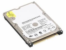
Figure 13. One spare strategy is to stock subcomponents that have a higher likelihood of failing, such as hard drives.
The strategy that you employ for stocking spare components should be dictated by the amount of downtime that you can accept. Regardless of the strategy that you choose, NI works to decrease the downtime of your PXI system by minimizing repair times for products that you return for repair, providing expedited repairs, and stocking replacements products around the world so that they can be delivered to you as quickly as possible.
Next Steps
For more information about building a test system, refer to Fundamentals of Building a Test System.