Digital I/O for Test, Control, and Design
Overview
Contents
- Digital I/O for Test and Measurement
- Digital I/O for Industrial Control and Automation
- Digital I/O for Design and Prototyping
- Related Links
Digital I/O for Test and Measurement
Most digital automated test equipment (ATE) systems generate and/or acquire patterns of 1’s and 0’s to communicate with a device under test (DUT). With recent innovations in digital components, however, these systems require a more sophisticated digital tester with capabilities beyond a simple logic analyzer with two on/off states. Faster chip speeds and the industry trend toward serial versus parallel digital protocols are necessitating ever higher sampling rates. In addition, manufacturing and time-to-market pressures are demanding hardware-level processing to complete tests quicker. Meanwhile, new logic families with variable voltage levels and single or differential signaling continue to make these tests more complex. National Instruments high-speed digital I/O (HSDIO) devices offer a range of digital ATE and stimulus-response features designed to meet the requirements of these high-end digital test applications.
- High clock and data rates up to 200 MHz and 400 Mb/s, respectively, deliver precise hardware-timed control essential for testing the latest integrated circuits, field-programmable gate arrays (FPGAs), and digital communication devices.
- Per-cycle, per-channel bidirectional control and real-time hardware comparison of acquired response data facilitate the development of applications such as bit error rate testing (BERT), failure analysis for verification and validation (V&V), and pass/fail manufacturing tests.
- Programmable voltage levels between -2.0 and 5.5 V create a flexible digital system that can interface with multiple logic families or characterize the upper and lower bounds of specific DUT.
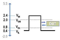
Figure 1. Programmable Voltage Levels
- Six logical channel states including logic low (0), logic high (1), tri-state (Z), compare logic high (H), compare logic low (L), and ignore (X) define digital test waveforms and control the actions of the digital tester.
- Multidevice synchronization offers down to subnanosecond synchronization for high-channel-count systems without the need for external wiring.
- Flexible handshaking modes provide synchronous and asynchronous exchange of signals to request and acknowledge data transfers between the test system and DUT.
Software is also a critical piece of any digital ATE. The NI Digital Waveform Editor is a graphical software tool you can use to visualize digital signals and easily create, edit, and modify digital waveforms for customized interfacing and test applications. You can design digital waveforms from scratch or import existing waveforms from design tools using Value Change Dump (.VCD) or ASCII file formats. In addition, as you acquire data, the Digital Waveform Editor can highlight bit errors, making it easy to visualize inconsistencies and measure timing requirements or update waveforms to eliminate design flaws. Combined with the NI LabVIEW graphical development environment and NI TestStand test management software, the Digital Waveform Editor completes the software component of any digital test system.
Table 1 summarizes the National Instruments high-speed digital I/O offering.
Family | Bus | Max Data Rate | Voltage | Number of Channels | Max Onboard Memory |
NI 654x | PCI, PXI | 100 Mb/s | 5.0, 3.3, 2.5, 1.8 V | 32 | 64 Mb/ch |
NI 653x | PCI Express, PXI Express | 50 Mb/s | 2.5, 3.3 V (5 V compatible) | 32 | 32 Mb/ch |
Table 1. National Instruments High-Speed Digital I/O Offering
Digital I/O for Industrial Control and Automation
Industrial applications often involve requirements beyond the capabilities of a typical measurement device. For example, many industrial sensors and actuators require 24 V logic levels and may operate at different voltage potentials that can cause ground loops. Safety for the measurement or control system and safety for the user or operator are equally important. With voltage levels up to 150 V, high current drive, and isolation, NI industrial digital I/O devices can connect directly to a wide array of industrial pumps, valves, motors, and other sensors/actuators while providing a high degree of safety and reliability.
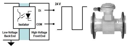
Figure 2. Industrial Measurements with 24 V Logic Levels and Isolation
These low-cost devices are ideal for industrial control and manufacturing test systems such as factory automation, embedded machine control, and production line verification. Furthermore, NI industrial digital I/O devices deliver a high-reliability industrial feature set designed to automate even the most demanding applications:
- Isolation reduces noise, offers an extended voltage range, and protects hardware for direct connection to industrial sensors and actuators.
- Programmable power-up states provide a known initialized state for safe operation when connected to pumps, motors, and other industrial actuators or machinery.
- Digital I/O watchdogs provide a fail-safe mechanism that monitors for computer or application crashes and place the system in a state to ensure safe recovery.
- Change detection automatically triggers your application to perform a digital read operation after a change-of-state event on a digital line with minimal processor usage.
- Programmable input filters remove chatter, noise, glitches, and spikes on inputs and provide debouncing for digital switches and relays.
- Industrial certifications from CE, FCC, C-Tick, UL, and VDE ensure EMI compliance in most regions of the world and certify that the system is safe to operate in hazardous environments.
Industrial DIO is part of the industrial DAQ suite of products that includes industrial NI M Series and S Series multifunction devices. These devices complement the NI programmable automation controller (PAC) platform, providing industrial I/O that integrates seamlessly with logic, motion, process control, and vision applications. NI PACs combine programmable logic controller (PLC) ruggedness with PC functionality under an open, flexible software architecture. Using LabVIEW, PACs with industrial DAQ and digital I/O can interface with existing PLC applications to add more advanced functionality into industrial machines and improve efficiency.
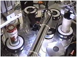
Figure 3. Innoventor Beverage Packaging System
Read more about the industrial feature set. Table 2 summarizes the NI industrial digital I/O offering.
Family | Bus | Max Number of Channels | Voltage | Isolation |
NI 650x | PCIe, PXIe, USB | 96 DIO | 5 V TTL/CMOS | — |
NI 652x | PCI, PXI | 24 DI, 24 DO | 60 to 150 V | Channel-to-channel |
NI 660x | PCI | 8 CTR | 5 V TTL, 48 VDC | Channel-to-channel |
Table 2. National Instruments Industrial Digital I/O Offering
Digital I/O for Design and Prototyping
Design is an inherently iterative process. No matter the scope of the application, every design cycle proceeds from definition to simulation, prototyping, and testing, and, more often than not, these stages are repeated throughout progressive revisions. Having the means to alternate quickly between stages is paramount to optimize the design process. Graphical system design with LabVIEW meets this need with a single platform encompassing the entire design cycle. Furthermore, reconfigurable hardware combined with the LabVIEW FPGA Module offers unmatched hardware and software flexibility for design, prototyping, and deployment.
Reconfigurable hardware features user-defined, onboard FPGA processing for complete control of system timing and triggering. You can configure the FPGA chip without any prior VHDL experience by creating LabVIEW block diagrams with the LabVIEW FPGA Module, giving you direct, immediate control over all the I/O. This process delivers high-performance, user-configurable timing and synchronization, as well as onboard decision making, at rates up to and exceeding 40 MHz.
For example, if you are developing applications with unsupported or custom digital communication protocols, you can use the LabVIEW FPGA Module to quickly implement or prototype different communication interfaces on FPGA-based R Series multifunction RIO hardware.
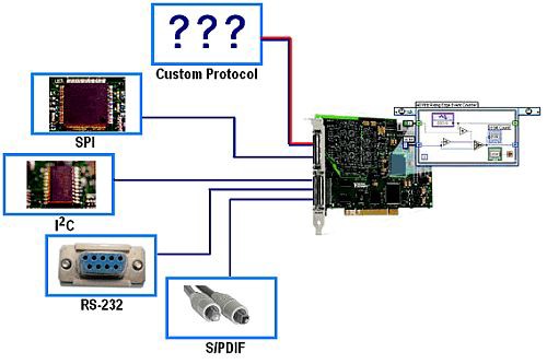
Figure 4. Custom Digital Protocols with R Series multifunction RIO and LabVIEW FPGA
Using LabVIEW FPGA, you can program each device’s “personality.” A personality is essentially a compiled bitfile containing configuration information that is downloaded to the onboard FPGA. Rather than use a device with a fixed personality or application-specific integrated circuit (ASIC), you have the ability to customize your board. Changing personalities as you proceed through the various iterations of a design cycle or prototype is as simple as modifying a LabVIEW block diagram and recompiling it. Once a personality is complete, LabVIEW FPGA is no longer required because the device may be accessed through LabVIEW for Windows or LabVIEW Real-Time. For more information on custom RIO personalities, see the related links below.
NI reconfigurable I/O hardware offers up to 160 digital lines that you can individually configure for input, output, counter/timer, pulse-width modulation, and more. Table 3 summarizes these options.
Family | Bus | DIO | Analog Inputs | Analog Outputs |
NI 783xR, 784xR, 785xR Reconfigurable Multifunction I/O Module | PCI, PXI, USB | 48 to 96 | 4 to 8 | 4 to 8 |
NI 781xR, NI 782x | PCI, PXI, PXIe | 128 to 160 | — | — |
Table 3. National Instruments R Series Multifunction RIO
NI high-speed digital I/O devices offer another option for many common tests incorporated in the digital device design process. For applications requiring high-speed stimulus-response tests or nonstandard voltage levels, for example, NI HSDIO devices complement multifunction RIO devices in the design cycle. HSDIO devices can also interface with higher-speed devices, transferring data at rates up to 400 Mb/s. Refer to the related links below for more information.