A Practical Guide to Machine Vision Lighting
Overview
Contents
- Introduction
- Vision Illumination Sources and Spectral Content
- The Cornerstones of Vision Illumination
- Considerations for an Optimal Lighting Solution
- Illumination Techniques
- Application Fields
- Sequence of Lighting Analysis
- Summary
- Related Links
Introduction
Perhaps no other aspect of vision system design and implementation has consistently caused more delays, cost overruns, and general consternation than lighting. Historically, lighting often was the last aspect specified, developed, or funded, if at all. This approach was not entirely unwarranted, as until recently there was no real vision-specific lighting on the market, meaning lighting solutions typically consisted of standard incandescent or fluorescent consumer products, with various amounts of ambient contribution.
This guide aims to present a standard method for developing sample-appropriate lighting rather than dwell on theoretical treatments. It details relevant aspects in a practical framework, with examples, where applicable, from the following areas:
- Knowledge of lighting types and application advantages and disadvantages, vision camera and sensor quantum efficiency and spectral range, illumination techniques and their application fields relative to surface flatness and surface reflectivity
- Familiarity with the four cornerstones of vision illumination: geometry, pattern or structure, wavelength, and filters
- Detailed analysis of the immediate inspection environment (physical constraints and requirements) and sample/light interactions with respect to your unique samples
When you have accumulated and analyzed the information from these areas, with respect to the specific sample and inspection requirements, you can achieve the primary goal of machine vision lighting analysis—to provide sample-appropriate lighting that meets three acceptance criteria consistently:
- Maximize the contrast on those features of interest
- Minimize the contrast elsewhere
- Provide for a measure of robustness
Each inspection is different, thus it is possible, for example, for lighting solutions that meet acceptance criteria one and two to be effective only provided there are no inconsistencies in part size, shape, orientation, placement, or environmental variables such as ambient light contribution (see Figure 1).
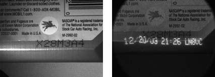
Figure 1. The cellophane wrappers on packs of note cards shows the left meets all three acceptance criteria whereas the right meets only criteria one and two. In this circumstance, the wrinkles are not precluding a good barcode reading. But what if the wrinkles were in a different place in the next pack on the line?

Vision Illumination Sources and Spectral Content
The lighting sources now commonly used in machine vision are fluorescent, quartz halogen, LED, metal halide (mercury), and xenon.
Fluorescent, quartz halogen, and LED are the most widely used lighting types in machine vision, particularly for small- to medium-scale inspection stations. Metal halide, xenon, and high-pressure sodium are more typically used in large-scale applications or in areas requiring a very bright source. Metal halide, also known as mercury, is often used in microscopy because it has many discrete wavelength peaks, which complements the use of filters for fluorescence studies. A xenon source is useful for applications requiring a very bright strobe light. Figure 2 shows the advantages and disadvantages of fluorescent, quartz halogen, and LED lighting types and relevant selection criteria, as applied to machine vision. For example, whereas LED lighting has a longer life expectancy, quartz halogen lighting may be the choice for a particular inspection because it offers greater intensity.
Figure 2. Comparison of common vision lighting sources.
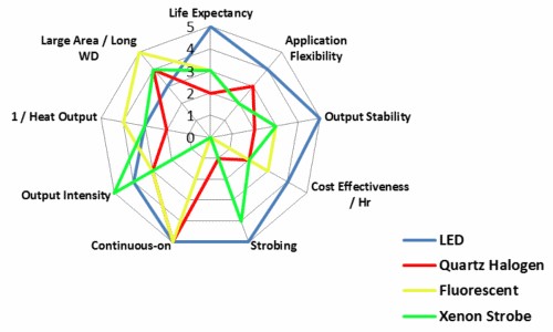
Historically, fluorescent and quartz halogen lighting sources have been used most commonly. In recent years, LED technology has improved in stability, intensity, and cost-effectiveness; however, it is still not as cost-effective for large area lighting, particularly compared with fluorescent sources. However, if application flexibility, output stability, and longevity are important parameters, then LED lighting might be more appropriate. Depending on the exact lighting requirements, oftentimes you can use more than one source type for a specific implementation, and most vision experts agree that one source type cannot adequately solve all lighting issues.
Consider not only a source’s brightness but also its spectral content (Figure 3). Microscopy applications, for example, often use a full-spectrum quartz halogen, xenon, or mercury source, particularly when imaging in color; however, a monochrome LED source is also useful for a black and white CCD camera, and also now for color applications, with the advent of “all color—RGB” and white LED light heads.
In those applications requiring high light intensity, such as high-speed inspections, it may be useful to match the source’s spectral output with the spectral sensitivity of your particular vision camera (Figure 4). For example, CMOS sensor-based cameras are more IR sensitive than their charge-coupled device (CCD) counterparts, imparting a significant sensitivity advantage in light-starved inspection settings when using IR LED or IR-rich Tungsten sources.
Figure 3. Light Source Relative Intensity Versus Spectral Content (The bar at the bottom denotes the approximate human visible wavelength range.)
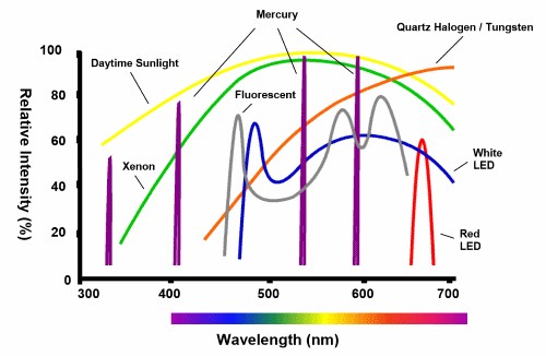
Figure 4. Camera Sensor Absolute Quantum Efficiency Versus Wavelength (The bar at the bottom denotes approximate human visible wavelength range.)
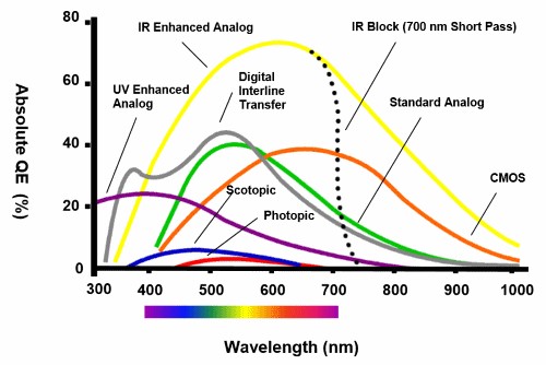
Additionally, Figures 3 and 4 illustrate several other relevant points to consider when selecting a camera and light source:
- Attempt to match your sensor’s peak sensitivity with your lighting source’s peak wavelength to take the fullest advantage of its output.
- Narrow wavelength sources, such as monochrome LEDs, or mercury are beneficial for passing strategic wavelengths when matched with narrow pass filters. For example, red 660 nm band pass filter, when matched to red LED light, is effective at blocking ambient light on the plant floor from overhead fluorescent or mercury sources.
- Sunlight has the raw intensity and broadband spectral content to call into question any vision inspection results–use an opaque housing.
- Even though your mind is good at interpreting what your eyes see, the human visual system is woefully inadequate in terms of ultimate sensitivity and spectral dynamic range–let your eyes view the image as acquired with the vision camera.
The Cornerstones of Vision Illumination
The 4 cornerstones of vision illumination are:
-
- Geometry—The 3-D spatial relationship among sample, light and camera
- Structure or Pattern—The shape of the light projected onto the sample
- Wavelength or Color—How the light is differentially reflected or absorbed by the sample and its immediate background
- Filters—Differentially blocking and passing wavelengths and/or light directions
Understanding how to manipulate and enhance sample contrast using the four cornerstones is crucial in meeting the three acceptance criteria for assessing the quality and robustness of lighting. Effecting contrast changes through geometry involves moving the sample, light, and/or camera positions until you find a suitable configuration. For example, a coaxial ring light (one mounted around the camera) may generate hotspot glare on a semireflective barcode surface, but by simply moving the light off-axis, the hotspot glare is also moved out of the camera’s view. Contrast changes through structure or the shape of the light projected on the sample is generally light head– or lighting technique–specific (see the Lighting Techniques section in Part 2 of this series). Contrast changes through color lighting are related to differential color absorbance versus reflectance (See Sample/Light Interaction).
Considerations for an Optimal Lighting Solution
With respect to the lighting environment, there are two aspects to evaluate when determining the optimal lighting solution: (1) immediate inspection environment and (2) sample/light interaction
Consider all the information from these evaluations together with the available optics, lighting types, techniques, and the four cornerstones to develop a sample-appropriate lighting solution that meets the three acceptance criteria.
Immediate Inspection Environment
Fully understanding the immediate inspection area’s physical requirements and limitations, in a 3D space, is critical. In particular, depending on the specific inspection requirements, the use of robotic pick-and-place machines or pre-existing, but necessary, support structures, may severely limit the choice of effective lighting solutions by forcing a compromise in not only the type of lighting but also its geometry, working distance, intensity, and pattern. For example, you may determine that a diffuse light source is required but cannot be applied because of limited close-up, top-down access. Inspection on high-speed lines may require intense continuous light or a strobe light to freeze motion, and of course large objects present an altogether different challenge for lighting. Additionally, consistent part placement and presentation are also important, particularly depending on which features are being inspected; however, even lighting for inconsistencies in part placement and presentation can be developed, as a last resort, if fully understood.
Ambient Light Contribution
The presence of ambient light input can have a tremendous impact on the quality and consistency of inspections, particularly when using a multispectral source such as white light. The most common ambient contributors are overhead factory lights and sunlight, but occasionally errant vision-specific task lighting from other inspection stations or even other stations in the same workcell can have an impact.
There are three active methods for dealing with ambient light: (1) high-power strobing with short duration pulses, (2) physical enclosures, and (3) pass filters. Which method is applied is a function of many factors, most of which are discussed in some detail in later sections. High-power strobing simply overwhelms and washes out the ambient contribution, but has disadvantages in ergonomics, cost, and implementation effort, plus not all sources, such as fluorescent, can be strobed. If you cannot employ strobing, and if the application calls for using a color camera, multispectral white light is necessary for accurate color reproduction and balance. In this circumstance, a narrow wavelength pass filter is ineffective, as it will block a major portion of the white light contribution, and thus an enclosure is the best choice.
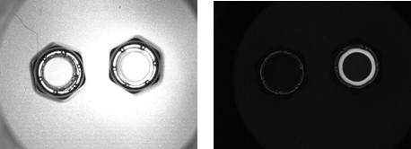
There are exceptions, however, to this general rule. For example, a 700 nm short pass filter, otherwise known as an IR blocker, is standard in color cameras because IR content can alter the color accuracy and balance, particularly of the green channel. Figure 5 illustrates how the use of a pass filter can block ambient light very effectively, particularly when the light of interest is low-yield fluorescence.
Figure 5. The left image shows nyloc nuts with a UV ring light, but flooded with red 660 nm “ambient” light. The goal is to determine nylon presence/absence. Given the large ambient contribution, it is difficult to get sufficient contrast from the relatively low-yield blue fluoresced light from the sample. The right image has the same lighting, except a 510 nm short pass filter was installed on the camera lens, effectively blocking the red “ambient” light and allowing the blue 450 nm light to pass.
Sample/Light Interactions
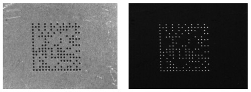
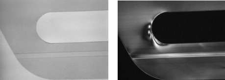
How a sample’s surface interacts with task-specific and ambient light is related to many factors, including the gross surface shape, geometry, and reflectivity as well as its composition, topography, and color. Some combination of these factors determines how much light, and in what manner, is reflected to the camera, and subsequently available for acquisition, processing, and measurement. For example, a curved, specular surface, such as the bottom of a soda can (Figure 6), reflects a directional light source differently from a flat, diffuse surface such as copy paper. Similarly, a topographic surface, such as a populated PCB, reflects differently from a flat but finely textured or dimpled (Figure 7) surface, depending on the light type and geometry.
Figure 6. On the left, the bottom of a soda can is illuminated with a bright field ring light but shows poor contrast, uneven lighting, and specular reflections. On the right, the soda can is imaged with diffuse light, creating an even background so the code can be read.
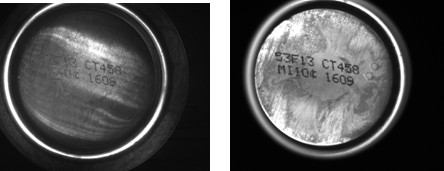
Figure 7. The 2D dot peen matrix code on the left is illuminated by bright field ring light. The right is imaged with a low angle linear dark field light. A simple change in light pattern creates a more effective and robust inspection.
Color Analysis
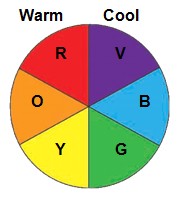
Figure 8 - Color Wheel
Materials reflect and/or absorb various wavelengths of light differentially, an effect that is valid for both black and white and color imaging space. Like colors reflect and surfaces are brightened; conversely, opposing colors absorb and surfaces are darkened. Using a simple color wheel of warm versus cool colors (Figure 8), you can generate differential contrast between a part and its background (Figure 9), and even differentiate color parts, given a limited, known palette of colors, with a black and white camera (Figure 10).
Figure 9. A mail stamp imaged under (a) red light, (b) green light, (c) blue light, generating less contrast than green, (d) white light, generating less contrast than either blue or green. White light contrasts all colors, but it may be a contrast compromise.
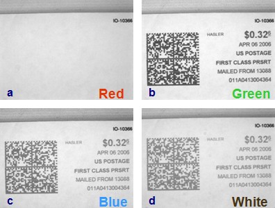
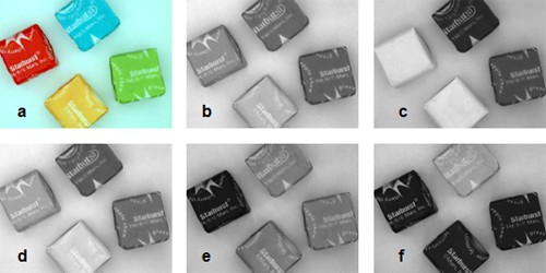
Figure 10. Candy pieces are imaged under (a) white light and a color CCD camera, (b) white light and a black and white camera, (c) red light, lightening both the red and yellow and darkening the blue, (d) red and green light, yielding yellow, lightening the yellow more than the red, (e) green light, lightening the green and blue and darkening the red, (f) blue light, lightening the blue and darkening the others.
Sample Composition and Transmittance
Sample composition can greatly affect what happens to task lighting impinging on a part. Some plastics may transmit light only of certain wavelength ranges and are otherwise opaque; some may not transmit, but rather internally diffuse the light; and still some may absorb the light only to re-emit it at the same wavelength or at a different wavelength (fluorescence). Fluorescence labels and dyes are commonly used in inks for the printing industry as well (Figure 11).
Figure 11. The motor oil bottle on the left is illuminated with a red 660 nm ring light. On the right, the bottle is illuminated with a 360 nm UV fluorescent light.
The properties of IR light can be useful in vision inspection for a variety of reasons. First, IR light is effective at neutralizing contrast differences based on color, primarily because reflection of IR light is based more on sample composition rather than color differences. You can use this property when less contrast, normally based on color reflectance from white light, is the effect you want (see Figure 12).
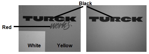
Figure 12. On the left, the glossy paper sample is under diffuse white light. The right is under diffuse IR light.
IR light is considerably more effective at penetrating polymer materials than the short wavelengths, such as UV or blue, and even red in some cases (see Figure 13). Conversely, it is this lack of penetration depth that makes blue light more useful for imaging shallow surface features of black rubber compounds or laser etchings, for instance.
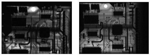
Figure 13. In the populated PCB the penetration of red is 660 nm (left image) and IR 880 nm light. Notice the better penetration of IR despite the red blooming out from the hole in the top center of the board.
Polarizing filters, when applied in pairs, one between the light and sample and the other between the sample and camera, and typically affixed to the lens through screw threads, are useful for detecting structural lattice damage in otherwise transparent samples (Figure 14).
Figure 14. On the left, a transparent plastic six-pack can holder is shown with a red back light. The right shows the same, except for the addition of a polarizer pair, showing stress fields in the polymer.
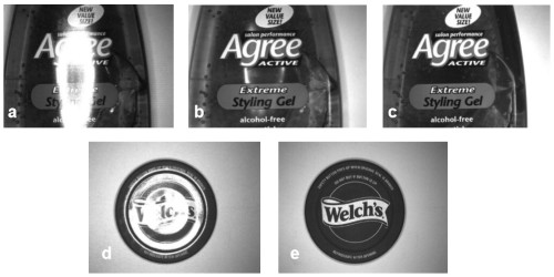
Particularly when used to block specular reflections on samples, any use of polarization filters comes with inherent compromises. The images depicted in Figure 15 demonstrate moderately effective and highly effective use of polarization filters specifically for blocking glare. In samples depicted in Figure 15a–c, you see that glare reflected from a curved surface, such as this personal care product bottle, can be controlled but not entirely eliminated (see Figure 15b center area). This is true because multiple reflection directions are produced on the curved surface from a directional light source, and polarization filters cannot block all vibration directions simultaneously, thus always leaving some areas vignetted. In this case, a more effective approach to glare control, given the flexibility to do so, is to reconsider the lighting geometry. By simple moving the light from a coaxial position around the lens to a relatively high angle, but off-axis position, you can completely eliminate all specular reflection. Conversely, for the relatively flat and planar jar top surface depicted in Figure 15d–e, you can largely remove the specular glare, producing a clear image for inspection. However, a caveat for using dual polarizers is that they can reduce the allowable light considerably—up to 2 ½ f-stops in the case of the jar top example, which could be detrimental for high-speed, light-starved inspections.
Figure 15. A change in light/sample, camera geometry, or type may be more effective than applying polarizers to stop glare. (a) Coaxial ring light without polarizers. (b) Coaxial ring light with polarizers (note some residual glare). (c) Off-axis (light axis parallel to the sample long axis) ring light without polarizers. (d) Coaxial ring light without polarizers. (e) Coaxial ring light with polarizers (note: 2 ½ f-stop opening).
Illumination Techniques
Illumination techniques comprise back lighting, diffuse (also known as full bright field) lighting, bright field (actually partial bright field or directional) lighting, and dark field lighting.
The application of some techniques requires a specific light and geometry, or relative placement of the camera, sample, and light—others do not. For example, a standard bright field bar light may also be used in dark-field mode; whereas a diffuse light is used exclusively as such.
Most manufacturers of vision lighting products also offer lights with various combinations of techniques available in the same light, and at least in the case of LED-based varieties, each of the techniques may be individually addressable. This circumstance allows for greater flexibility and also reduces potential costs when many different inspections can be accomplished in a single station rather than two. If the application conditions and limitations of each of these lighting techniques, as well as the intricacies of the inspection environment and sample/light interactions are well understood, it is possible to develop an effective lighting solution that meets the three acceptance criteria.
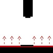 Figure 16. Back Lighting | Back Lighting Back lighting generates instant contrast as it creates dark silhouettes against a bright background (Figure 16). The most common uses are for detecting the presence/absence of holes and gaps, part placing or orientating, or measuring objects. Often it is useful to use a monochrome light, such as red, green, or blue, with light control polarization if precise (subpixel) edge detection becomes necessary. |
|
|
Diffuse (Full Bright Field) Lighting Diffuse, or full bright field lighting, is most commonly used on shiny specular or mixed reflectivity samples where even but multidirectional light is needed. Several implementations of diffuse lighting are generally available, but there are three primary types (Figures 17a–c), with hemispherical dome/cylinder or on-axis being the most common.
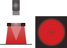
Diffuse dome lights are effective at lighting curved, specular surfaces, commonly found in the automotive industry, for example. On-axis lights work in a similar fashion for flat samples and are particularly effective at enhancing differentially angled, textured, or topographic features on relatively flat objects. To be effective, diffuse lights, particularly dome varieties, require close proximity to the sample.
A useful property of axial diffuse lighting is that in this case, rather than rejecting or avoiding specular glare, you may actually take advantage of the glare if it can be isolated specifically to uniquely define the feature(s) of interest required for a consistent and robust inspection. |
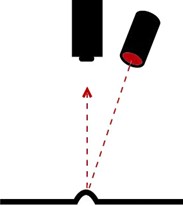 Figure 18. Directional Bright Field |
Partial Bright Field or Directional Lighting Partial bright field lighting is the most commonly used vision lighting technique, and is the most familiar lighting used every day, including sunlight. This type of lighting is distinguished from full bright field in that it is directional, typically from a point source and, because of its directional nature, it is a good choice for generating contrast and enhancing topographic detail. It is much less effective, however when used on-axis with specular surfaces, generating the familiar “hotspot” reflection. |
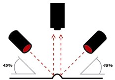 Figure 19. Dark Field Lighting | Dark Field Lighting Dark field lighting is perhaps the least well understood of all the techniques, although you do use these techniques in everyday life. For example, the use of automobile headlights relies on light incident at low angles on the road surface, reflecting back from the small surface imperfections, and also nearby objects. |

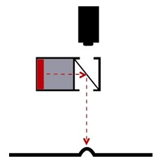
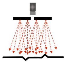 Figure 17c. Flat Diffuse
Dark field lighting can be subdivided into circular and linear, or directional types, the former requiring a specific light head geometry design. This type of lighting is characterized by low or medium angle of light incidence, typically requiring close proximity, particularly for the circular light head varieties (Figure 19).
Bright Field Versus Dark Field
The following figures illustrate the differences in implementation and result of circular directional (partial bright field) and circular dark field lights on a mirrored surface.
|
Figure 20a. Bright Field Image of a Mirror | 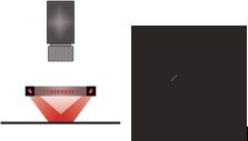 Figure 20b. Dark Field Image of a Mirror (note scratch) |
Effective application of dark field lighting relies on the fact that much of the light incident on a mirrored surface that would otherwise flood the scene as a hotspot glare, is reflected away from rather than toward the camera. The relatively small amount of light that is reflected back into the camera is what happened to catch an edge of a small feature on the surface, satisfying the “angle of reflection equals the angle of incidence” equation (see Figure 21 for another example).
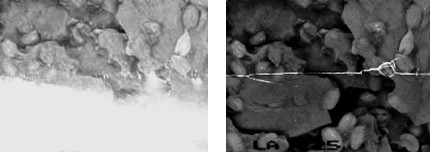
Figure 21. The peanut brittle bag on the left is under a bright field ring light. On the right, it is under a dark field ring light—note the seam is very visible.
Application Fields
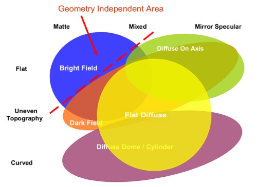
Figure 22 illustrates potential application fields for the different lighting techniques based on the two most prevalent gross surface characteristics: (1) surface flatness and texture and (2) surface reflectivity.
This diagram plots surface reflectivity, divided into three categories—matte, mirror, and mixed—versus surface flatness and texture or topography. As you move right and downward on the diagram, more specialized lighting geometries and structured lighting types are necessary.
As might be expected, the Geometry Independent Area implies that relatively flat and diffuse surfaces do not require specific lighting, but rather any light technique may be effective, provided it meets all the other criteria necessary, such as working distance, access, brightness, and projected pattern.
Figure 22. Lighting Technique Application Fields: Surface Shape Versus Surface Reflectivity Detail (Although not shown, any light technique is generally effective in the Geometry Independent Area of the diagram.)
Sequence of Lighting Analysis
The following sequence of lighting analysis assumes a working knowledge of lighting types, camera sensitivities, and optics and familiarity with illumination techniques and the four cornerstones of vision illumination. You can use it as a checklist, but it is by no means comprehensive. It does, however, provide a good working foundation for a standardized method that you can modify and/or expand for the inspection’s requirements.
- Immediate Inspection Physical Environment
- Physical Constraints
- Access for camera, lens, and lighting in a 3-D space (working volume)
- The size and shape of the working volume
- Min and max camera, lighting working distance and field-of-view
- Part Characteristics
- Sample stationary, moving, or indexed?
- If moving or indexed, speeds, feeds, and expected cycle time?
- Strobing? Expected pulse rate, on-time, and duty cycle?
- Are there any continuous or shock vibrations?
- Is the part presented consistently in orientation and position?
- Any potential for ambient light contamination?
- Ergonomics and Safety
- Man-in-the-loop for operator interaction?
- Safety related to strobing or intense lighting applications?
- Physical Constraints
- Sample/Light Interactions
- Sample surface
- Reflectivity—Diffuse, specular, or mixed?
- Overall geometry—Flat, curved, or mixed?
- Texture—Smooth, polished, rough, irregular, multiple?
- Topography—Flat, multiple elevations, angles?
- Light intensity needed?
- Composition and Color
- Metallic, non-metallic, mixed, polymer?
- Part color vs. background color
- Transparent, semi-transparent, or opaque - IR transmission?
- UV dye, or fluorescent polymer?
- Light Contamination
- Ambient contribution from overhead or operator station lighting?
- Light contamination from another inspection station?
- Light contamination from the same inspection station?
- Sample surface
- Features of Interest
- Applying the Four Cornerstones of Lighting
- Light—Camera sample geometry issues
- Light pattern issues
- Color differences between sample and background
- Filters for short, long, or band pass applications including polarization
- Lighting Techniques and Types Knowledge
- Fluorescent versus Quartz-Halogen vs. LED vs. others
- Bright field, dark field, diffuse, or back lighting
- Vision camera and sensor quantum efficiency and spectral range
Summary
This level of in-depth analysis can and often does result in seemingly contradictory directions, and a compromise is necessary. For example, detailed sample/light interaction analysis might point to the use of the dark field lighting technique, but the inspection environment analysis indicates that the light must be remote from the part. In this instance, a more intense linear bar light(s) oriented in dark field configuration may create the contrast you want, but perhaps require more image post-processing.
No matter the level of analysis, and understanding, there is quite often no substitute for actually testing the two or three light types and techniques first on the bench, then in actual floor implementation whenever possible. And when designing the vision inspection and parts handling/presentation from scratch, it is best to get the lighting solution in place first, then build the remainder of the inspection around the lighting requirements.
The objective of this detailed analysis and application of what might be termed a “tool box” of lighting types, techniques, tips, and tricks is to help you arrive at an optimal lighting solution that takes into account and balances issues of ergonomics, cost, efficiency, and consistent application. This helps you to better direct your time, effort, and resources—items better used in other critical aspects of vision system design, testing, and implementation.
Related Links
Learn more about machine vision topics including optics, camera selection, and FPGA image processing.:
- Learn more about NI machine vision hardware products
- Learn more about Vision Development Module software