From Friday, April 19th (11:00 PM CDT) through Saturday, April 20th (2:00 PM CDT), 2024, ni.com will undergo system upgrades that may result in temporary service interruption.
We appreciate your patience as we improve our online experience.
From Friday, April 19th (11:00 PM CDT) through Saturday, April 20th (2:00 PM CDT), 2024, ni.com will undergo system upgrades that may result in temporary service interruption.
We appreciate your patience as we improve our online experience.
From an instrumentation standpoint, current measurements are made with front end conditioning or sensors such as shunts, current transformers (CT), hall-effect sensors, and Rogowski coils. NI has a variety of hardware options for both direct measurement with a module and connection to external sensors and conditioning equipment. Table 1 shows modules compatible with CompactRIO chassis and CompactDAQ chassis for current measurement.
All modules listed in table 1 use simultaneous sampled inputs with a 50kS/s 24-bit ADC per channel. Current and Voltage measurement modules from tables 1 and 2 respectively are synchronized when installed together in either a CompactDAQ or CompactRIO chassis. Channel synchronization is needed for more accurate phase and power measurements.
| Model Number | Measurement Range | Current Measurement Method |
|---|---|---|
| NI 9239 / NI 9229 | ±10 V/±60 V | Connect to current sensors with ±10V or ±60V output |
| NI 9238 | ±0.5 V | Connect to current sensors with 0.333 VRMS output and external shunts |
| NI 9227 | 5 ARMS | Direct connection to module that has internal, calibrated shunts |
| NI 9246 | 20 ARMS | Direct connection to module that has internal, calibrated CTs; OR connect to 1 A and 5A secondary from high current CTs |
| NI 9247 | 50 ARMS (100 ARMS for 10 seconds) | Direct connection to module that has internal, calibrated CTs; OR connect to 1 A and 5A secondary from high current CTs |
Table 1: NI has a variety of C Series modules for current measurement. All modules output full waveform for processing with LabVIEW or other measurement and analysis software.
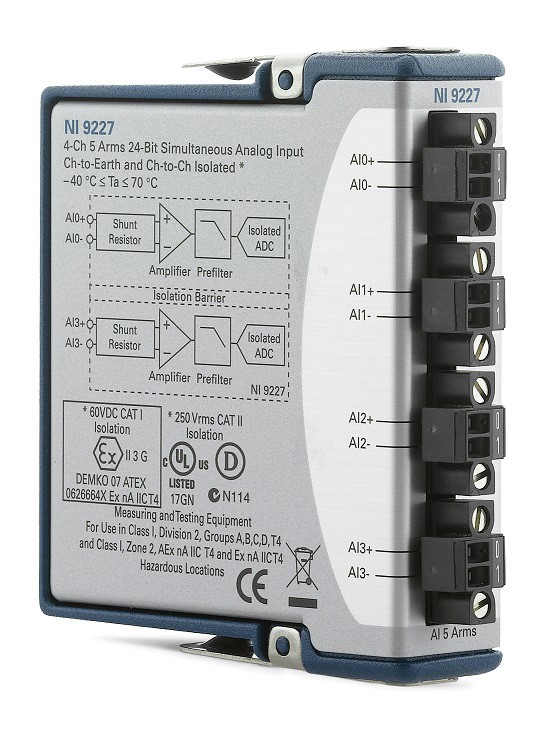 | 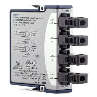 |
Figure 1: The NI 9229, NI 9239, NI 9227, and NI 9238 have a two terminal connector (left) for each measurement channel. Shields are available (right), and recommended, for strain relief and operator keep-outs from connections to active circuits.
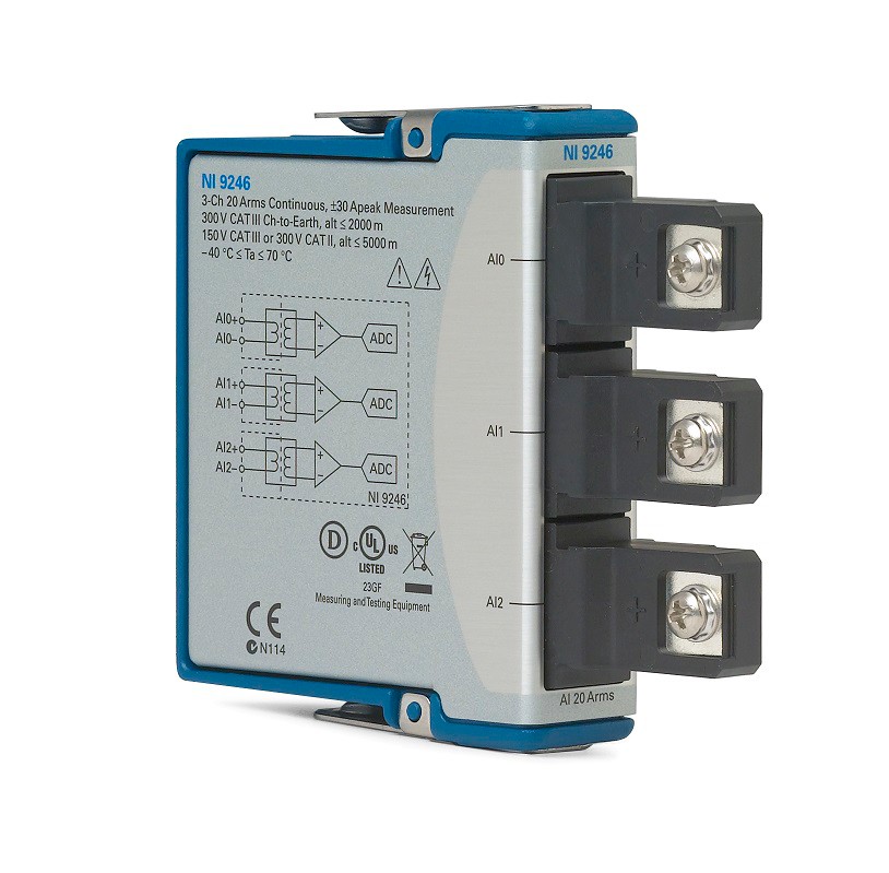 | 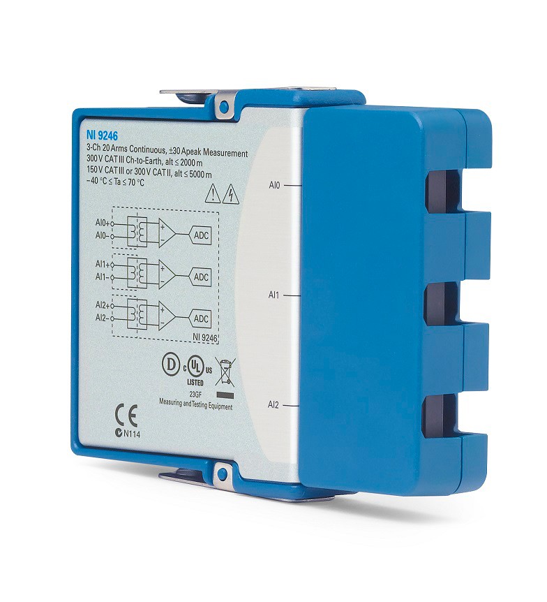 |
Figure 2: The NI 9246 and NI 9247 modules have CTs built into the module, large over-current ratings, and accommodate up to 10AWG wire with ring lugs for higher current measurement. Direct measurements with these modules will be more accurate and with a higher frequency response than using most external CTs/sensors. Both modules can withstand 500 ARMS for 1 second and 1250 ARMS for 1 cycle.
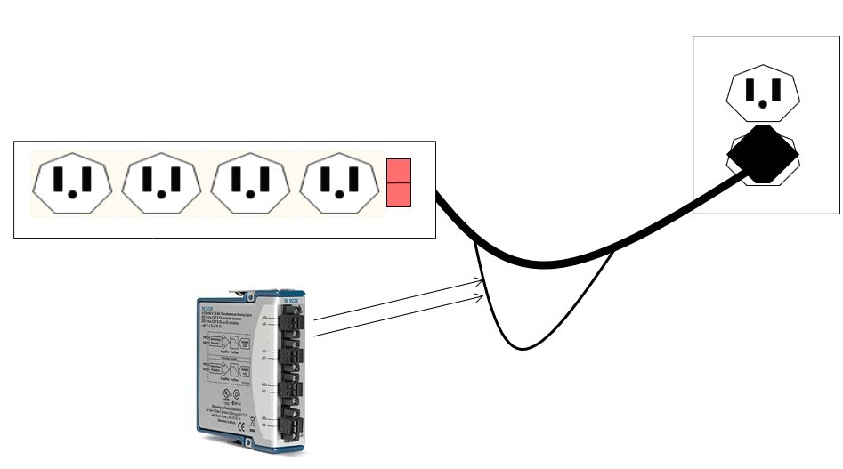
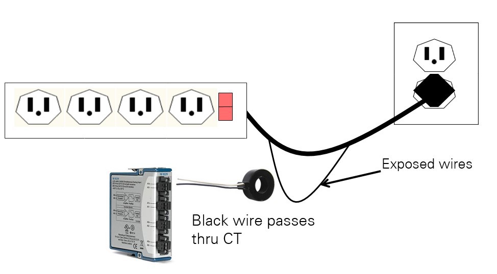
The following illustrations show how to physically connect modules to a circuit for current measurement. A power strip connected to a residential outlet is used for demonstration purposes but this concept scales from individual appliances on residential service levels (120VAC/240VAC), all the way to utility voltages. NOTE: Utility distribution and transmission levels will always use external sensors (CTs/PTs).
Figure 3: For direct module connection, the load wire (black in the US), is cut and connected to the AI+ and AI- terminals of a single channel. Current passing through the module is measured. In the image above with the splice in the cable, the module will measure the current flowing to all devices plugged into the power strip.
Figure 4: For module measurement using a CT, the load wire (black in the US), is passed through the opening of the CT either via a split core CT or cutting/re-splicing the wire. The leads from the CT are then connected to the AI+ and AI- of the measurement module. The module will measure all current on the line that is routed through the CT opening. Scaling is done in software to convert from the Voltage/Amp output from the sensor to the full scale Amperage on the circuit.
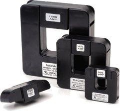
Current transformers (CTs) are sensors used to linearly step down the current passing through the sensor to a lower level compatible with measurement instrumentation. The core of a current transformer is toroidal, or ringed, in shape with an opening in the center. Wire is wrapped around the core to form the secondary and covered by a shroud or plastic casing. The number of wire windings around the core dictates the step down ratio, or CT ratio, between the current in the measured line (primary), and the current output connected to the instrumentation (secondary). The load wire to be measured is passed through the opening in the center of the current transformer. Example: A CT with a ratio of 500:5 means that a 500 ARMS load on the main line will result in an output of 5 ARMS on the CT secondary. The instrument will measure 5 ARMS at the terminals and can apply a scaling factor input by the user to display the full 500 ARMS. CTs are specified with a nominal value but often the accuracy is listed to over 100% of nominal. CTs can be split core or solid core. Split core CTs hinge open or have a removable section to let the installer connect the CT around a load wire without physically disconnecting the load wire to be measured.
Safety Alert: Though the CT can physically connect around an installed line, the power should be safely disconnected before installation of a CT. Open secondary connections with power on the primary can lead to extremely hazardous Voltage potentials.
CT options when purchasing include nominal range, opening diameter, split/solid core, output type (voltage/current), and output range (0.333VRMS, ±10V, 1ARMS, 5ARMS, etc.). CT vendors can often customize a sensor for specific needs such as input or output range.
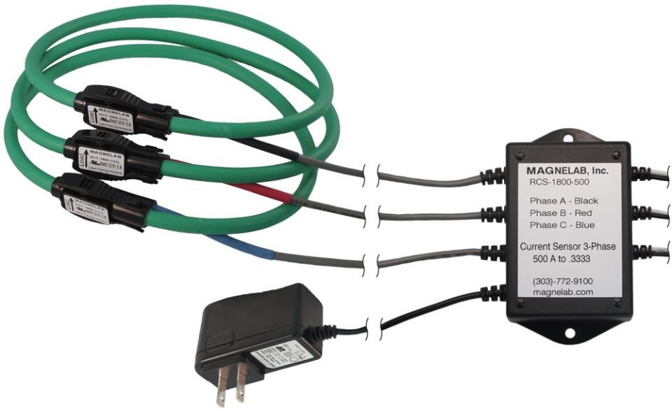
Figure 5: Split core CTs typically have a hinge or removable section for installation around a line without physical disassembly, though the power should still be disconnected. (Image courtesy of Magnelab)
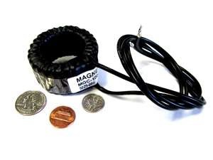
Figure 6: Solid core CTs are lower cost but can require more labor to install on circuits that are already operational.
(Image courtesy of Magnelab)
Bandwidth of 1kHz to 2kHz is sufficient for most AC circuit power quality applications. For higher frequency applications connect directly to the NI 9246 or NI 9247 for up to 24kHz bandwidth or select higher frequency CTs that are more expensive. All of the modules listed in the table above have a bandwidth of approximately 24 kHz for signals directly connected. High frequency CTs are more specialized and have bandwidth specifications in the hundreds of MHz range. The NI 9215, NI 9222, and NI 9223 measurement modules sample rates range from 100kS/s/ch to 1MS/s/ch at 16-bits of resolution for higher frequency measurements.
For high frequency measurements beyond the capabilities of the NI 9223, NI recommends a scope or digitizer for PXI designed for lab, research, and test systems.
CTs do not measure DC curent or the DC offset component of an AC signal. For most AC power applications this is not necessary. When DC measurement is needed, the NI 9227 has built-in calibrated shunts and can measure DC current up to 5 Amps. To measure more than 5 Amps DC, a high power current measurement shunt (see below) or Hall Effect sensor (see below) connected to the appropriate measurement module is used.
Rogowski coils, sometimes referred to as “rope CTs”, are another sensor option for measuring current in a line. Rogowski coils are similar in that they wrap around the load wire but they are flexible, have a much larger opening than standard CTs, and the principle of measurement is different. Rogowski coils induce a voltage that is proportional to the rate of change of Current and thus require in integrator circuit to convert to proportional current. The integrator is a separate box/component that is usually panel or DIN rail mounted, requires a DC power supply, and outputs low voltage or current signals to the instrumentation. The size and flexibility of Rogowski coils make them well suited for looping around larger bus bars found in commercial buildings or factories, especially when they are already built and power measurement is added as a retrofit, but they are more expensive than a CT of comparable input range.
Figure 7: Rogowski coils require external power, integration circuitry (located in the black mountable box in the image above), and are more expensive than typical solid/split core CTs, but offer fast phase response and are good for retrofit installations and large bus bar measurements due to their large flexible opening. (Image courtesy of Magnelab)
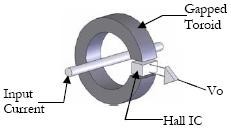
Hall Effect sensors are based on the “Hall Effect”, named after Edwin Hall, where current flow through a semiconductor placed perpendicular to a magnetic field will generate a voltage potential across the semiconductor material. For the purposes of current measurement, Hall Effect circuitry is placed perpendicular in the core the magnetic field and output a voltage that is scaled to the current load in the measured line. Hall Effect CTs typically have a better frequency response and can measure DC offset, but are more expensive, require power, and can be subject to temperature drift.
Figure 8: Hall Effect sensors have a sensing circuit perpendicular to the magnetic field and requires power. Hall Effect sensors are not subject to saturation limits like a CT and can measure DC currents, but are more costly.
Current measurement shunts, or current shunt resistors, are resistors placed in the circuit for the purpose of measuring the current that flows across the shunt. These are fairly common electrical components and exist for a variety of applications. Sizing a shunt will be based on measurement current range, output range, and power flowing through the circuit. More expensive precision resistors are available for more accuracy. Shunts do not wrap around the circuit wire and are placed in-line as a component. This eliminates an isolation barrier between the measured circuit and the measurement equipment and can make the install more difficult than a CT or Rogowski Coil. Shunts however, can measure DC currents, have better frequency response and a better phase response. The NI 9238 module for CompactRIO and CompactDAQ was designed with a low range analog front end (±0.5V) specifically for current shunt resistors. Additionally, the NI 9238 features 250V of channel-to-channel isolation.
The following 3rd party companies have current and voltage measurement transformers, Hall Effect Sensors, and/or Rogowski Coils in their catalog. Current shunt resistors are often sold by electronic component distributors such as Digi-Key Electronics.
Magnelab offers a variety of voltage and current measurement products including current transformers (CTs), potential transformers (PTs), Rogowski coils, high frequency CTs, and more in a variety of output signal levels.
Verivolt has a variety of sensors, connectors, and isolation products designed for power measurement applications. Additionally, several sensors have high bandwidth capability and BNC connectivity options for quick connection to BNC measurement modules such as the NI 9223, NI 9222, and NI 9215.
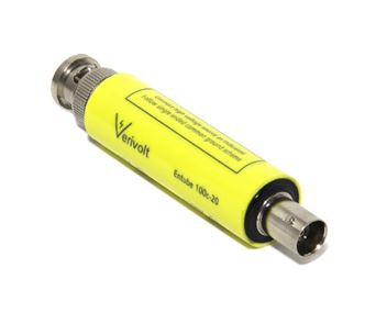 | 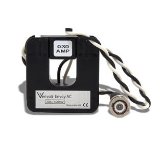 | 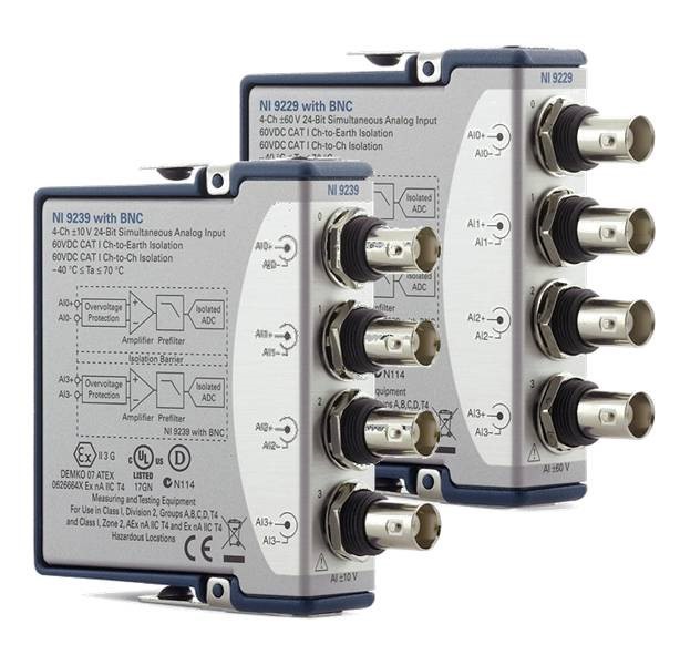 |
Figure 9: Verivolt has a variety of sensors with BNC connectivity that can connect directly to any NI module with BNC connectors. Analog input modules with BNC connectivity include the NI 9229, NI 9239, NI 9215, NI 9222, and NI 9223. (Images left / center curtesy of Verivolt)
In the scope of this paper, voltage measurements refer to AC power systems at industrial and utility voltage levels that range from 120VRMS for regional residential service to over 750kV for extra high voltage (EHV) systems on a transmission system for an electrical grid. Instrumentation designed for high voltage utility applications incorporate requirements such as safety, larger gage wire terminals, higher thermal dissipation, and specific certification tests. Most instrumentation designed for AC power measurement has an input range of several hundred Volts. Higher voltages, above 1,000 VAC, typically require an external potential transformer (PT) to step the Voltage to be measured down to a range that is compatible with most instrumentation.
Similar to the current measurement modules, all modules listed in table 2 use simultaneous sampled inputs with a 50kS/s 24-bit ADC per channel. CompactDAQ and CompactRIO chassis will synchronize the voltage measurement modules in the table below with the current measurement modules listed in table 1, which is needed for more accurate phase and power measurements.
| Model Number | Measurement Range | Measurement Technology Used |
|---|---|---|
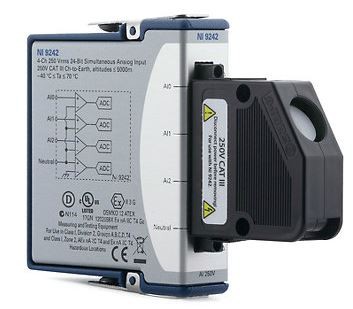
| NI 9242 | 250 VRMS L-N | Direct measurement for 120/240 AC systems. Connection to external PTs with a 120/240 VRMS secondary for high voltage measurement. |
| NI 9244 | 400 VRMS L-N | Direct measurement for up to 690 VRMS L-L systems. |
| NI 9225 | 300 VRMS AI+ to AI- | Direct measurement for up to 300 VRMS systems |
| NI 9238 | ±0.5 V | Connection to 0.333 V sensors |
| NI 9239 | ±10 V | Connection to 10 V sensors |
| NI 9229 | ±60 V | Connection to 60 V sensors |
Table 2: NI has a variety of C Series modules for all forms of Voltage measurement. All modules output full waveform data for processing with LabVIEW or other measurement and analysis software.
Figure 10: The NI 9242/44 have large input terminals and high over-voltage protection for use in AC power and utility applications. (shown with included protective shell installed)
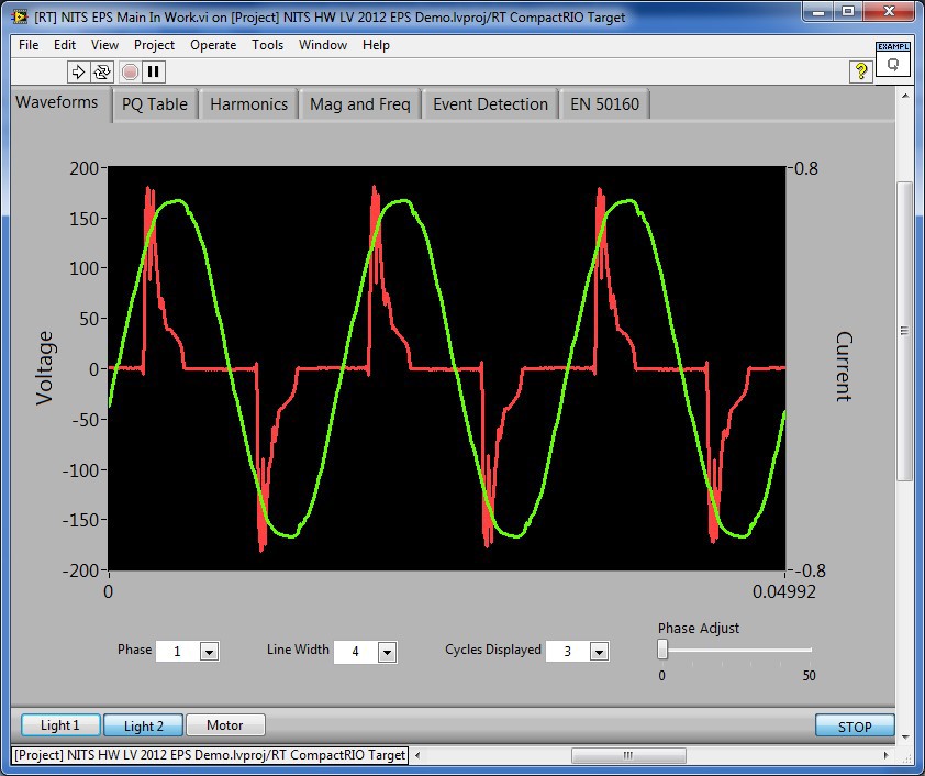
High speed measurement equipment, as described in this paper, provides waveform data similar to the image below. In this data capture from LabVIEW, the green waveform is the Voltage waveform from a 120 VRMS office outlet, and the red waveform is the corresponding current measurement for an older compact fluorescent lightbulb. The voltage measurement module and current measurement module are synchronized through shared signals in the CompactDAQ or CompactRIO chassis. This is important for some applications as phase shift between the voltage and current waveforms is one parameter of power quality that is monitored and without simultaneous sampling it is difficult to determine whether that shift is from the instrumentation or the circuit.
Figure 11: Design a LabVIEW front panel to display waveform data and power calculation results.
At this point in the measurement system, waveform data from the modules is used to calculate any power quality parameter desired. Some of these calculations are fairly simple while others are complex calculations aggregated over several cycles, seconds, or minutes to determine the ultimate quality.
LabVIEW has several function palettes designed for waveform and signal processing and offers additional toolkits for power waveform processing and calculations. The NI LabVIEW Electrical Power Toolkit provides analysis functions for all of the fundamental power calculations discussed in this paper and is available for download online. The following analysis functions are included with the Full version of the NI LabVIEW Electrical Power Toolkit and conform to the IEC 61000-4-30:2008 standard:
The following analysis functions conform to the EN 50160:2007 standard:
The NI-DAQmx driver for CompactDAQ has API support for LabVIEW, C, C++, Measurement Studio, and can support saving data to open file formats for use in Excel or other software programming languages.
It is important to note for text based programmers that the analysis VIs from the Electrical Power Toolkit are only available for the LabVIEW development environment and not available for use with CVI, C, C++, or Measurement Studio.
Asset monitoring systems are used to prevent failure in critical devices, such as large pumps, fans, belts, etc., by monitoring physical and electrical parameters to intelligently determine when a machine needs to be maintained. The current signature of a large motor can help detect inefficiencies like unbalance, or mechanical failures like broken rotor bars. Table 3, below, lists the recommended product components for a motor monitoring application.
| Component | NI Product | Description |
|---|---|---|
| Voltage Input | NI 9244 (Up to 400 VAC L-N,690 VAC L-L) NI 9242 (Up to 250 VAC L-N, 400 VAC L-L) | Large industrial motors will typically run on distribution service level voltages and require an external PT to connect to the NI 9242. Lower voltage motors under 690VAC, can directly connect to the NI 9244 |
| Current Input | NI 9239 with low voltage CT | Low voltage CTs are safer and easier to work with than 1A/5A CTs. Be sure to size the CT and the selected low voltage module with in-rush current in mind which can be 10X the steady state current. |
| Chassis and Controller | CompactRIO | The built in processor lets the system run continuously. Processed data can be stored locally, sent back to a SCADA system, or trigger alarms to the SCADA system or local PLCs. |
| Software (text based) | NI Linux Real-Time C/C++ Cross-Compile Toolchain | For system developers who already have algorithms developed in C or C++, the NI Linux Real-Time Cross Compile Toolchain can be used to program the multicore processor of the CompactRIO Controller. The FPGA is still programmed in LabVIEW. |
Table 3: Recommended components of a permanently installed motor monitoring system.
Computer based test systems for residential or commercial appliances increase the productivity of the design and test teams while improving the quality of the product. One classification of tests is for R&D purposes, such as:
Additionally, appliance test systems can be built for automated manufacturing line tests ensuring the device powers on, LEDs are operating. Table 4, below, lists the recommended product components for an appliance or electrical device test system.
| Component | NI Product | Description |
|---|---|---|
| Voltage Input | NI 9244 (Up to 690VAC)
| Most residential and commercial appliances will run under the 3-Phase 690VAC range of the NI 9244. |
| Current Input | NI 9247 | The NI 9247 high current input module has built in, calibrated CTs for continuous measurement up to 50ARMS per phase and can measure up to 100ARMS for 10 seconds to capture inrush events. |
| Chassis and Controller | NI CompactDAQ & a multi-core PC. | NI CompactDAQ has 4,8 and 14 slot with USB or Ethernet connection back to a PC. All modules in the chassis will be synchronized and with 1 slot for Voltage, and 1 slot for Current, there will be available slots for temperature, pressure, flow, digital, and a host of other sensor modules for the appliance test. |
| Software (graphical) | LabVIEW Electrical Power Toolkit | The Electrical Power Toolkit includes the PMU toolkit and Protection IP toolkit. Additionally, the PMU program that ships with the NI Grid Automation System is available for download as an open LabVIEW project. |
| Software (text based) | NI-DAQmx (driver included with HW) | The NI-DAQmx driver for CompactDAQ includes support for a variety of text based languages such as C/C++, C#, Visual Studio .NET |
Table 4: Recommended components of an appliance or other mixed sensor electrical device test system.
Applications for NI hardware in the utility industry cover use in grid devices for measurement, control, and protection, such as:
Table 5, below, lists the recommended product components for intelligent systems deployed to a utility grid in a substation control house, equipment yard, or in a distribution system pole or pad mount enclosure.
| Component | NI Product | Description |
|---|---|---|
| Voltage Input | NI 9242 | The NI 9242 was designed to connect to 120VRMS and 240VRMS PTs found in substations, transformers, and breakers. For low voltage PTs, use the NI 9238, NI 9239, or NI 9229 as appropriate. |
Current Input | NI 9247 | The NI 9247 high current input module has built in, calibrated CTs for continuous measurement up to 50ARMS and 100ARMS for 10 seconds. Withstand ranges are 500ARMS for 1 second and 1250ARMS for 1 cycle. |
| Chassis and Controller | NI CompactRIO | The Linux RTOS, programmable FPGA, multi-core processing options, and rugged operating specs make CompactRIO the ideal choice for intelligent grid device design. |
| Software (graphical) | LabVIEW | LabVIEW is the industry standard for test software. Add the Electrical Power Toolkit and Vibration Measurement Suite for even more pre-built measurement capability. Build reports, dashboards, store data in multiple file formats, and connect to over 4,000 3rd party instruments with available drivers on the LabVIEW Driver Network. |
| Software (text based) | C/C++ with Eclipse | For system developers that already have algorithms developed in C or C++, the Eclipse development environment can be used to program the multi-core processor of CompactRIO. The programmable FPGA is still programmed in LabVIEW. |
Table 5: Recommended components for intelligent measurement and control devices deployed to an electrical grid.
The best quality measurement for Voltage, Current and power will be from using modules and instrumentation that offers direct measurement in the module, as with the NI 9227, NI 9246, or NI 9247. Remember to consider all pertinent operating ranges (steady state, in-rush/start-up, fault, etc.) of the circuit when selecting the input/output range of the CT and the input range of the instrumentation module. From this default the following table can serve as a rough guide for other sensors options. (not a definitive answer as many factors can influence selection) Consult sensor vendors, like Magnelab and Verivolt, for further advice on ultimate sensor selection.
Starting with a direct module connection as the default choice use the following table as guidance.
| Current Measurement System Need | Recommendation |
|---|---|
| Best accuracy for under 5ARMS measurement | NI 9227 (5A) |
| DC measurement | NI 9227 (5A) |
| Over-current protection (500ARMS for 1 sec., 1250A for 1 cycle) | NI 9246 (20A) or NI 9247 (50A) |
| Continuous (steady-state) measurement range up to 50ARMS with 10sec measurement up to 100ARMS | NI 9247 (50A) |
| Input range greater than 50ARMS | External CT with voltage output to a voltage input module |
| Measure without coupling/splicing the instrument into the circuit | External CT with voltage output to a voltage input module |
| Install in a location where it is difficult to install a solid or split core CT (Bus bar, tight wiring, etc.) | Rogowski coil to a voltage input module |
| DC measurement with greater than 5A range | Hall Effect Sensor or current shunt resistors |
| DC measurement without coupling/splicing the instrument into the circuit | Hall Effect Sensor |
| Greater than 50ARMS input range with a sensor that outputs 1A or 5A on the secondary (Utility applications) | Connect 1A/5A CT secondary to NI 9246 or NI 9247. |
| Reduce cost per channel and can trade off some resolution and dynamic measurement quality | Use CTs and PTs with less than ±10V output and connect to an NI 9220, 16-ch simultaneous input module. (100kS/s/ch) |
| Need better accuracy on DC currents | Precision shunt resistor or a PXI DMM |
| Need higher bandwidth? Up to 500kHz | Use high frequency CTs and PTs with less than ±10 output and connect to NI 9215, NI 9222, or NI 9223. |
| Need higher bandwidth? >500 kHz | PXI Scope/Digitizer |
Table 6: Guidance for selecting a current measurement solution.
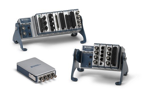
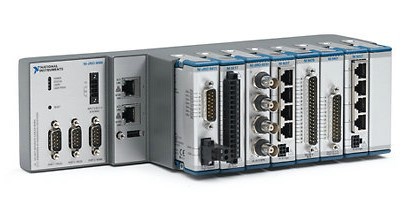
CompactRIO and CompactDAQ are chassis-based systems designed for test, measurement, control, and monitoring. With over 100 measurement modules available, you can design a custom mixed measurement solution that meets your needs in a single instrument. For power applications, you can add more circuit measurements by adding more modules in the same chassis or combine power with other measurements like temperature, pressure, and vibration for complete R&D test systems or comprehensive asset monitoring systems.
NI CompactDAQ chassis are available in 1, 4, 8, and 14 slot options and use USB, WiFi, or ENET connectivity for communication back to a Windows PC. CompactDAQ Controllers are also available and essentially have a built in computer eliminating the need for an external PC. CompactDAQ Controllers are designed for mobile, rugged, or headless (no connected UI), monitoring and test operations.
Learn more about CompactDAQ.
CompactRIO is a programmable control and monitoring system with a multi-core processor, real-time operating system, programmable FPGA, and compatibility with all C Series modules from NI and 3rd party companies. CompactRIO lets domain experts build embedded I/O controllers and monitoring systems to help them solve their problems.
Learn more about CompactRIO.