From 11:00 PM CST Friday, Apr 11th - 1:30 PM CST Saturday, Apr 12th, ni.com will undergo system upgrades that may result in temporary service interruption.
We appreciate your patience as we improve our online experience.
From 11:00 PM CST Friday, Apr 11th - 1:30 PM CST Saturday, Apr 12th, ni.com will undergo system upgrades that may result in temporary service interruption.
We appreciate your patience as we improve our online experience.
The EtherCAT RIO expansion chassis and set of industrial communication drivers support an open, real-time Ethernet protocol called EtherCAT. EtherCAT is well suited for high-speed I/O and control applications that need determinism and synchronization. In this white paper, learn the fundamentals of EtherCAT technology as it applies to NI products, including protocol basics, data transfers, and distributed clock synchronization.
EtherCAT (Ethernet Control Automation Technology) is a high-performance, industrial communication protocol for deterministic Ethernet. It extends the IEEE 802.3 Ethernet standard to transfer data with predictable timing and precise synchronization. Managed by the EtherCAT Technology Group, this open standard has been published as part of the IEC 61158 and is commonly used in applications such as machine design and motion control.
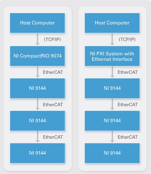
EtherCAT implements a master/slave architecture over standard Ethernet cabling. EtherCAT masters from National Instruments consist of real-time controllers with dual Ethernet ports such as NI CompactRIO, PXI, and industrial controllers. Each NI slave also contains two ports that permit daisy chaining from the master controller.
Figure 1. EtherCAT Master/Slave Architecture With NI Hardware
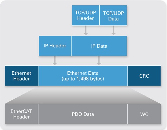
The EtherCAT protocol transports data directly within a standard Ethernet frame without changing its basic structure. When the master controller and slave devices are on the same subnet, the EtherCAT protocol merely replaces the Internet Protocol (IP) in the Ethernet frame.
Figure 2. Ethernet Frame Structure With EtherCAT
Data is communicated between master and slaves in the form of process data objects (PDOs). Each PDO has an address to one particular slave or multiple slaves, and this “data and address” combination (plus the working counter for validation) makes up an EtherCAT telegram. One Ethernet frame can contain multiple telegrams, and multiple frames may be necessary to hold all the telegrams needed for one control cycle.
With some real-time protocols, the master controller sends a data packet and must wait for the process data to be interpreted and copied at every slave node. However, this method of determinism may be difficult to sustain because the master controller must add and manage a certain amount of processing time and jitter per slave.
EtherCAT technology overcomes these system limitations by processing each Ethernet frame on the fly. For example, suppose the Ethernet frame is a moving train, and the EtherCAT telegrams are train cars. The bits of PDO data are people in the cars who can be extracted or inserted by the appropriate slaves. The whole “train” passes through all the slave devices without stopping, and the end slave sends it back through all the slaves again.
Figure 3. EtherCAT Data Transfers
In the same way, when device 1 encounters the Ethernet packet sent by the master, it automatically begins streaming the packet to device 2, all while reading and writing to the packet with only a few nanoseconds of delay. Because the packet continues passing from slave to slave to slave, it could be present in multiple devices at the same time.
What does this mean practically? Consider having 50 slave devices, and different data is sent to each slave. For non-EtherCAT implementations, this may mean sending 50 different packets. For EtherCAT, one long packet that touches all slaves is sent, and the packet contains 50 devices’ worth of data. However, if all the slaves need to receive the same data, one short packet is sent, and the slaves all look at the same part of the packet as it is streaming through, which optimizes the data transfer speed and bandwidth.
EtherCAT is designed to achieve high performance and high channel counts for single-point applications such as control. Because slave reads and writes can occur in the same frame, the EtherCAT telegram structure is optimized for decentralized I/O. Plus, the complete protocol processing takes place within hardware and is thus independent of the run time of protocol stacks, CPU performance, or software implementation. Also, each NI slave device uses several fieldbus memory management units (FMMUs) dedicated to PDO transfers and address examination. The slaves, not the master, are in charge of mapping the appropriate telegrams to themselves, so this reduces the complexity of the master and frees its resources.
Another factor in achieving deterministic networks is the master controller’s responsibility to synchronize all slave devices with the same time using distributed clocks. One of the slave devices must contain the master clock that synchronizes the other slave devices’ clocks. For NI implementation, the first slave device is designated with the master clock, and the master controller sends a special synchronization telegram to read the master clock in every scan cycle. This telegram then updates and realigns the clocks on all the other slave devices to prevent drifting.
Accurate synchronization is particularly important when widely distributed processes require simultaneous actions such as coordinated motion between motion axes. NI uses timestamps to measure the time difference between the leaving and returning frame. In this way, propagation delay is calculated between nodes, and precise synchronization (less than 1 µs) can be achieved by the exact adjustment of distributed clocks.
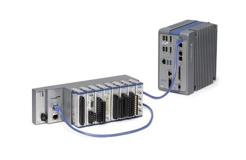
National Instruments offers a variety of platforms that are compatible with deterministic distributed I/O over EtherCAT. For the master controller, you may use an NI CompactRIO controller with two Ethernet ports, a PXI system with an NI PXI-8231/8232 Ethernet interface, or an industrial controller. Then you may daisy chain multiple NI 9144 or NI 9145 slave chassis from the controller to expand your time-critical applications while maintaining hard determinism with minimal processor resources. The NI 9144 and NI 9145 are rugged 8-slot chassis that work with more than 50 C Series modules that cover a wide variety of analog, digital, motion, and specialty I/O. These I/O modules provide direct sensor connectivity as well as reusability with other NI hardware platforms and form factors.
Figure 4. NI Industrial Controller With NI 9145 Slave Chassis
Best of all, the out-of-the-box experience has greatly minimized any configuration for NI EtherCAT slave chassis by automatically recognizing all connected slaves and their modules in the NI LabVIEW graphical programming environment. With the LabVIEW Real-Time Module, you have easy access to the physical channels using the click-and-drag I/O variable, live test panels, and I/O forcing for troubleshooting.
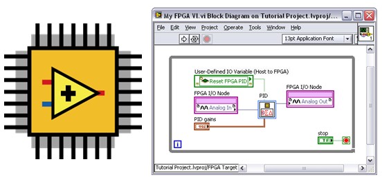
With the LabVIEW FPGA Module, you can embed hardware-level logic on each NI slave to offload processing power from the master controller and reduce response time by making decisions directly at the node. You can also take waveform measurements, use the field-programmable gate array (FPGA) to conduct onboard analysis, and then pass the single-point results back to the controller.
Learn more about Programming EtherCAT I/O with the LabVIEW FPGA Module.
Figure 5. NI LabVIEW provides easy graphical programming tools for the NI EtherCAT master and the EtherCAT slave chassis field-programmable gate array (FPGA) chip.